Coin dispenser

a coin dispenser and coin technology, applied in the field of coins dispensers, can solve the problems of inability to combine coins with different diameters and/or thicknesses on the same extraction disc, limited coin range, and inability to extract two thin coins and/or coins with small diameters, so as to prevent the drawbacks of the system known, efficient coin distribution

Active Publication Date: 2012-11-01
AZKOYEN
View PDF0 Cites 1 Cited by
  • Summary
  • Abstract
  • Description
  • Claims
  • Application Information

AI Technical Summary

Benefits of technology

[0014]The object of the present invention is a coin dispenser issuing coins efficiently as a unit and preventing the drawbacks of the systems known in the state of the art.

Problems solved by technology

Devices of this type are suitable for extracting different coins but with the limitation that the cavities must have a suitable geometry to extract the coin with larger diameter and / or thickness and that at the same time two thin coins and / or coins with small diameter cannot be extracted.
This limitation means that this coin dispenser must be modified depending of the range of coins with larger and smaller desired diameter and / or thickness, in some cases the compatibility of coins with different diameters and / or thicknesses with the same extraction disc being impossible.
This system is less complex than other trigger systems but it still has ranges of coins limitations, defining a system having a movable trigger and an adjustment plate for different ranges of coins being necessary.
This device behaves better with respect to the amount of discs used for extracting coins but it continues to have range limitations.
With the described constitution, the two retractable arched gates make up the means for controlling the exit of the coins from all the cavities, such that the operation problems of any of the gates could alter the operation of the entire dispenser.
On the other hand, the limitation of coins with the smallest diameter allowed is established by the shape demarcated by the ribs of the lower face of the disc in each of the cavities, which may allow housing two coins the sum of the diameters of which slightly exceeds that of the cavities, causing the simultaneous exit of the two coins or a jam.
This feature limits the range of allowed coin diameters.

Method used


Image

  • Coin dispenser
  • Coin dispenser
  • Coin dispenser

Examples


Embodiment Construction

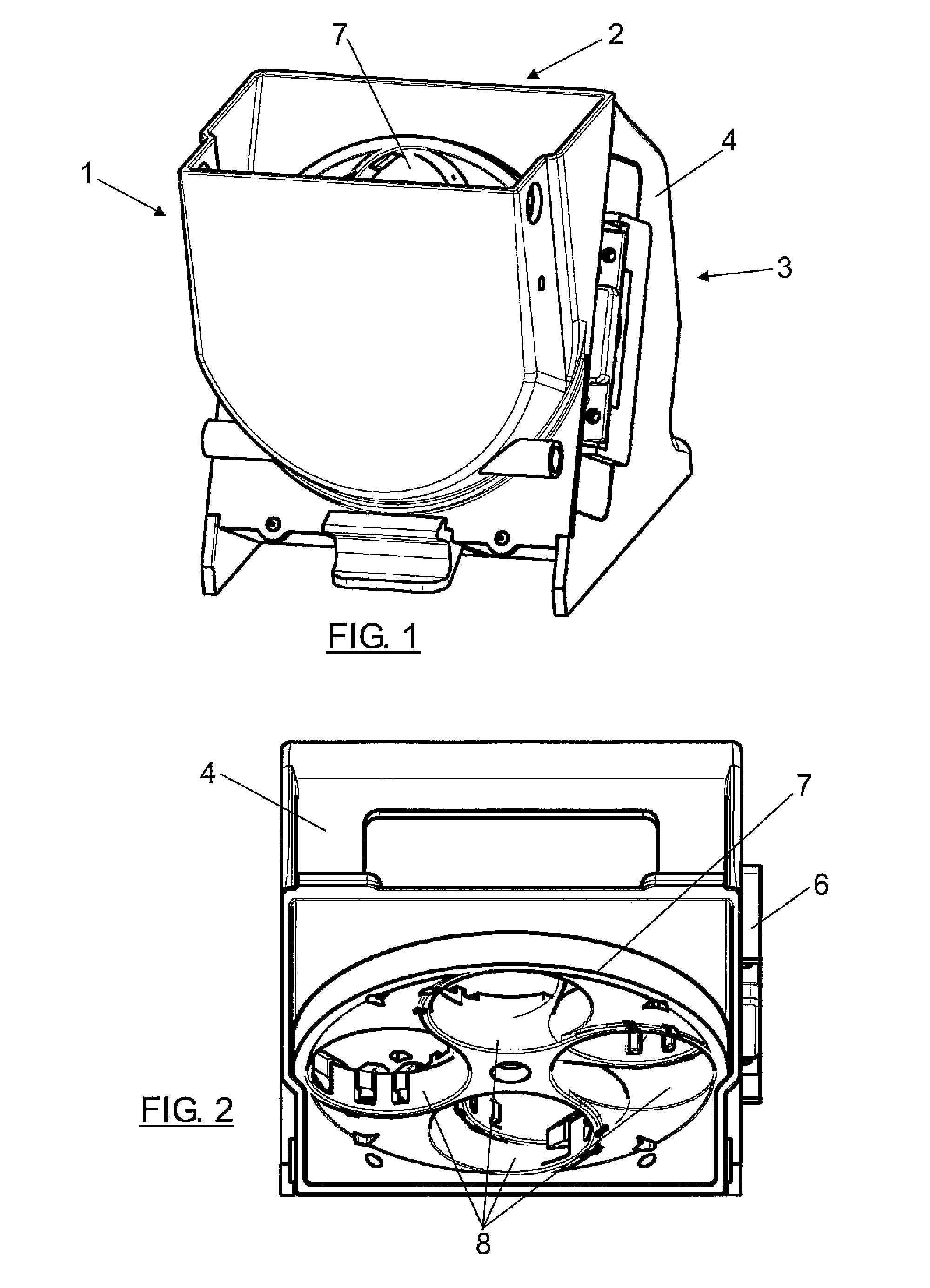
[0059]FIG. 1 shows a coin dispenser formed according to the invention, which is made up of a coin storing unit 1, with loading mouth 2, and a coin extractor 3 comprising a casing 4 to which the storing unit 1 is fixed.

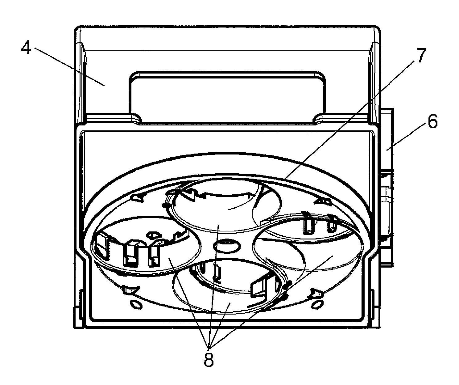
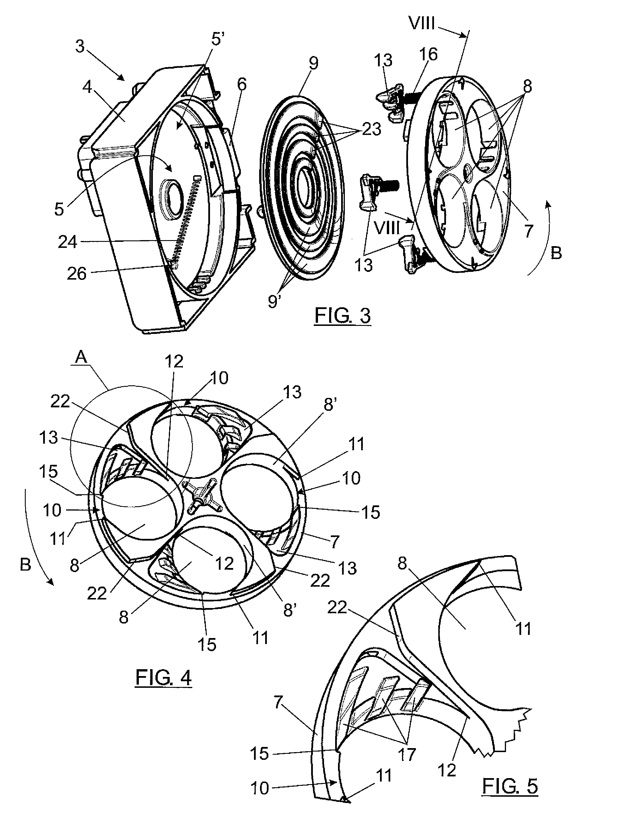
[0060]As can be seen in FIG. 3, the casing 4 defines a cylindrical chamber 5 having a side outlet 6 for the exit of coins, as will be discussed below. A driving disc 7 limiting and closing the storing unit 1 on one side, FIG. 1, is housed in the chamber 5.

[0061]Other components not depicted, such as a geared motor for operating the driving disc 7, coin level and exit sensors, electronic control, etc., not depicted and all those having known arrangement, are additionally assembled on the casing 4.

[0062]The driving disc 7 has circumferentially distributed cylindrical cavities 8, which are closed, on the side opposite to that occupied by the coin storing unit 1, by a supporting base which in the depicted example is configured in the form of a base disc 9, arranged between...


PUM


Abstract

A coin dispenser including a coin storing unit (1) and a coin extractor (3), the casing of which (4) demarcates a cylindrical chamber (5) with side outlet (6) for the exit of coins, in which there is housed a rotary driving disc (7) which has a series of cavities (8) closed, on the side opposite to that occupied by the coin storing unit, by a base disc (9) forming stops (14) opposite the rotation direction of the driving disc (7). The disc has retractable parts (13) which, together with the stops (23), control the exit of coins driven in the cavities (8).

Description

[0001]This application claims benefit of Serial No. 201130673, filed 28 Apr. 2011 and Serial No. 201230370 filed 13 Mar. 2012 in Spain and which applications are incorporated herein by reference. To the extent appropriate, a claim of priority is made to each of the above disclosed applications.FIELD OF THE INVENTION[0002]The present invention relates to a coin dispenser intended to be used as a unit for issuing coins in applications such as automatic vending machines, gaming machines, parking meters, etc.[0003]The dispenser of the invention is of the type comprising a coin storing unit and a coin extracting unit.[0004]More specifically the dispenser of the invention is of the type the extractor of which is made up of a casing defining a cylindrical chamber with a side outlet in which there is housed a rotary driving disc limiting the coin storing unit on one side and having a series of cavities which are closed on the side opposite to that occupied by the coin storing unit by a supp...

Claims


Application Information

Patent Timeline
Patent Type & Authority Applications(United States)
IPC IPC(8): G07D1/00
CPCH01G9/12G07D9/008
Inventor CALLEJA LAFUENTE, MIGUEL A.LACARRA FERNANDEZ, OSCARMARTINEZ CHAVOY, ALVAROSOLA SANCHEZ, BERNARDOJIMENEZ ZOZAYA, SILVIAIRURITA LOYARTE, JUAN MIGUEL
Owner AZKOYEN
Why Eureka
Try Eureka