Method and apparatus for delivering cement paste into a bone cavity

a technology of cement paste and bone cavity, which is applied in the direction of instruments, prostheses, packaged goods, etc., can solve the problems of poor material properties, complicated design of the delivery tool, and higher costs,

Active Publication Date: 2012-11-01
LIN JIIN HUEY CHERN +1
View PDF6 Cites 10 Cited by
  • Summary
  • Abstract
  • Description
  • Claims
  • Application Information

AI Technical Summary

Problems solved by technology

However, larger pressures require more complicated designs in the delivery tool as well as higher costs.
This problem becomes especially serious in delivering a highly viscous paste, such as PMMA and calcium-based cement.
Although a more dilute paste prepared with a higher liquid / powder ratio may make the paste flow and be pushed through the small exit more easily, unfortunately, a dilute paste almost always leads to poor material properties.
This is a big dilemma in this field.
Practically, however, in so doing, an extremely long container is required.
(A plunger of the same length is also required to drive the paste all the way to the container exit) This kind of length is practically impossible for any kind of surgery.
Furthermore, even if an extremely long, thin container is used, it would be practically impossible to transport the mixed cement paste into this thin container.
When a regular syringe is used, the large cross-sectional difference-induced problem still remains in the transportation of the paste from the syringe into the thin container.
Another primary problem with the conventional syringe-type cement deliverer is that a larger pressure does not guarantee a more efficient delivery.
Due to this solid-liquid separation effect, the cement paste coming out of the container at the early stage has a higher-than-desired liquid / powder ratio, causing properties of the cement to degrade.
On the other hand, the cement remaining in the container, especially at the later stage, has a lower-than-desired liquid / powder ratio (because the lower-density liquid continues to be squeezed out of the container) and becomes difficult to flow out of the exit.

Method used


Image

  • Method and apparatus for delivering cement paste into a bone cavity
  • Method and apparatus for delivering cement paste into a bone cavity
  • Method and apparatus for delivering cement paste into a bone cavity

Examples


Embodiment Construction

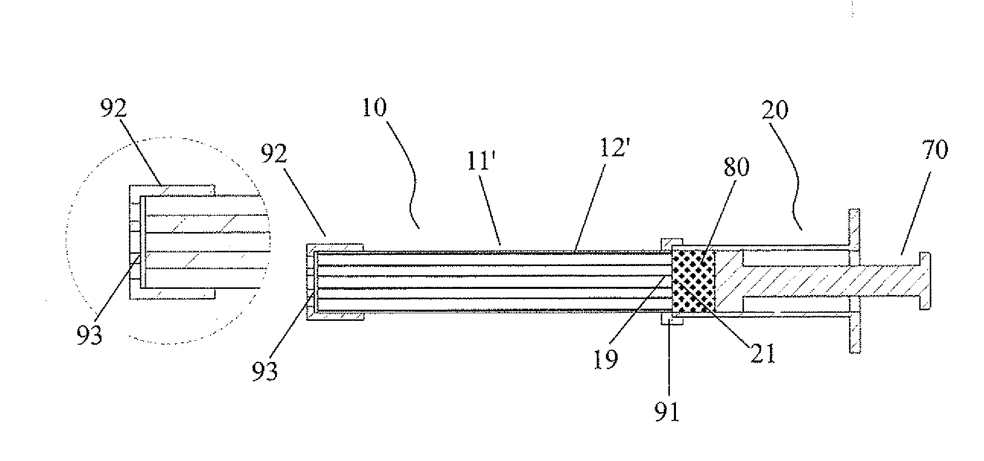
[0030]In the following, a general term “filler” is used to represent the cement paste, and the drug powder paste, viscous fluid or gel.

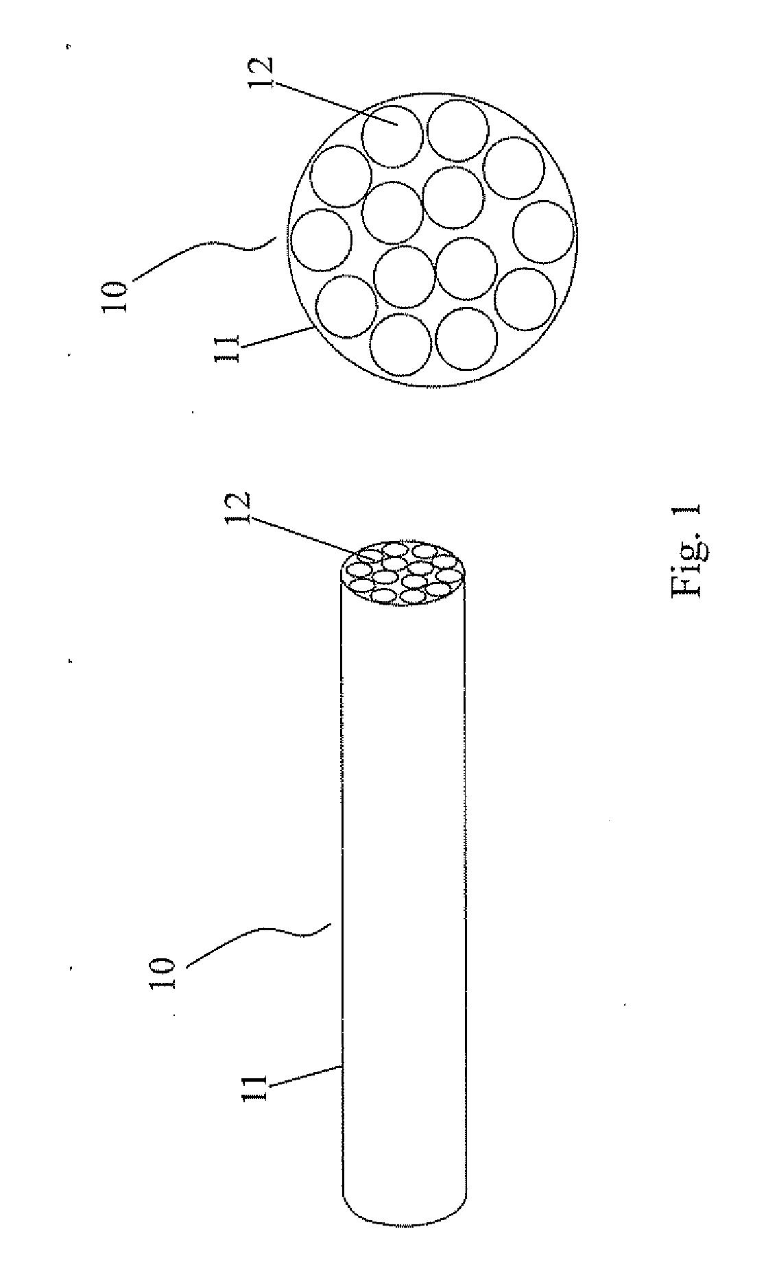
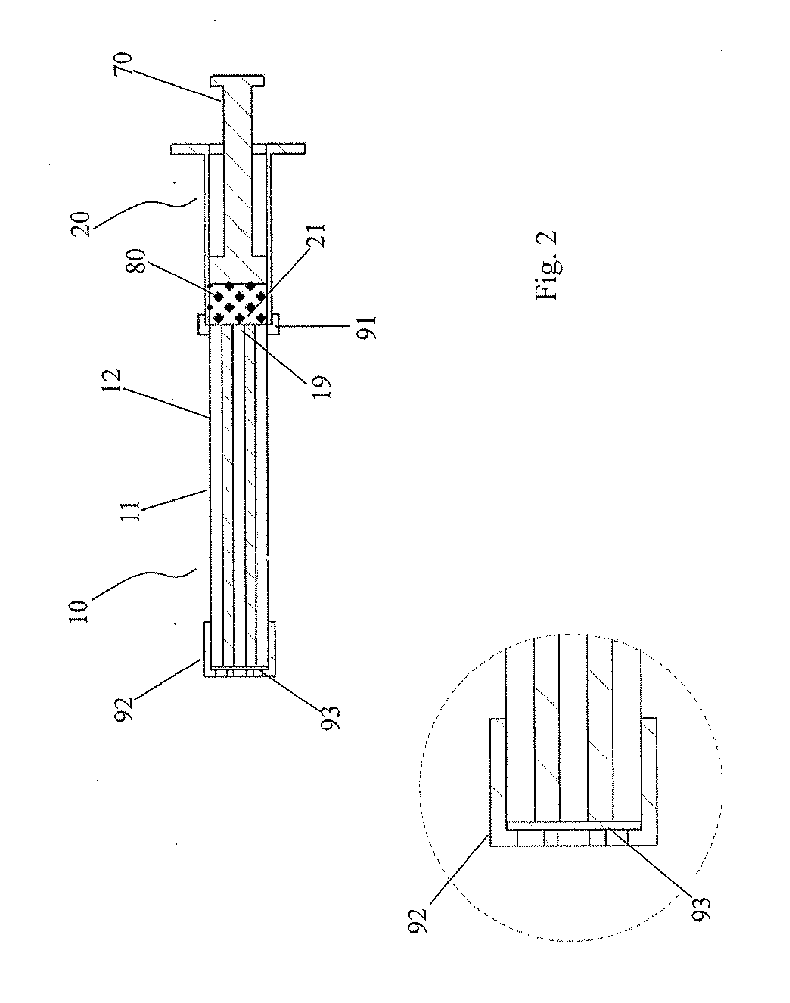
[0031]A filling apparatus constructed according to one embodiment of the present invention comprises a plurality of parallel tunnels formed in a longitudinal body and in a longitudinal direction of said body; and a filler reservoir having an exit end adapted to be in fluid communication with said plurality of parallel tunnels, wherein a cross-sectional area of said exit end is less than about 5 times of a total cross-sectional area of said plurality of parallel tunnels.

[0032]Preferably, said tunnels have an inner diameter of about 1 mm to about 10.0 mm and a length of about 10.0 mm to about 300 mm.

[0033]Preferably, the cross-sectional area of said exit end is less than about 3 times of a total cross-sectional area of said plurality of parallel tunnels, and more preferably about 1.5 to about 1.1 times of a total cross-sectional area of said plurality ...


PUM

PropertyMeasurementUnit
lengthaaaaaaaaaa
inner diameteraaaaaaaaaa
lengthaaaaaaaaaa

Abstract

The present invention is related to a technique for simultaneously forming a plurality of paste filled tunnels. The plurality of paste filled tunnels are connected to a surgical tube directly or indirectly and emptied one after another, until a desired amount of the paste is injected into a bone cavity, organ or a tissue via the surgical tube. The paste may be a bone cement paste, a drug powder paste, viscous fluid or gel. The injected bone cement paste will set in the bone cavity to act as a medical implant.

Description

CROSS-REFERENCE TO RELATED APPLICATION[0001]This patent application claims the benefit of U.S. Provisional Patent Application No. 61 / 479,421, filed Apr. 27, 2011.FIELD OF THE INVENTION[0002]The present invention is related to a technique for simultaneously forming a plurality of cement paste filled tunnels which are adapted to be connected to a surgical tube. The present invention is also related to a method for injecting a cement paste into a bone cavity, in which the cement paste will set to act as a medical implant.BACKGROUND OF THE INVENTION[0003]A common method for delivering a cement paste (or any other highly viscous paste) into a bone (or other tissue or organ of a diseased subject) cavity by a minimally invasive procedure is by pressing the paste into the cavity through a thin tube percutaneously inserted into the cavity. To fill in a bony cavity, PMMA and calcium-based cements are most commonly used. The cement paste is generally prepared by mixing a solid powder component...

Claims


Application Information

Patent Timeline
Patent Type & Authority Applications(United States)
IPC IPC(8): A61B17/58
CPCA61B17/8816A61B17/8822B65B3/003B65B3/12A61B17/8833A61B17/3472A61M5/14G01F11/025
Inventor LIN, JIIN-HUEY CHERNJU, CHIEN-PING
Owner LIN JIIN HUEY CHERN
Why Eureka
Try Eureka