Tracheal tube comprising trachea sealing portion

a technology of sealing portion and trachea, which is applied in the field of tracheal tubes, can solve the problems of endotracheal longitudinal folds and pulmonary aspiration, and achieve the effects of preventing endotracheal aspiration, reducing the pressure of volume inflators, and improving sealing

Inactive Publication Date: 2012-11-08
SEOUL NAT UNIV BUNDANG HOSPITAL
View PDF7 Cites 5 Cited by
  • Summary
  • Abstract
  • Description
  • Claims
  • Application Information

AI Technical Summary

Benefits of technology

[0009]Another aspect of the present invention is to provide a method for preventing endotracheal aspiration using the tracheal tube.
[0056]In accordance with another aspect of the present invention, there is provided a method for preventing endotracheal aspiration by providing a medium through the conduits of the tracheal tube.
[0057]The tracheal tube according to the present invention can reduce the pressure of volume inflators, i.e. two cuffs, and supply a medium to a trachea sealing portion, which is positioned between the two cuffs, to improve the sealing effect. The tracheal tube according to the present invention can reduce pulmonary aspiration, and thus prevent VAP to a considerable extent. The tracheal tube according to the present invention is applicable to all types of patients in need of tracheal tubes, such as a patient in a serious condition requiring mechanical ventilation, a patient requiring ventilation through a tube inserted into a tracheostomy stoma, a patient undergoing general anesthesia, etc.

Problems solved by technology

Such a use of an endotracheal tube, however, causes a number of problems in connection with secretions that gradually pass between the inner surface of the trachea and the outer surface of the cuff.
Conventional tracheal tubes of the HVLP (High Volume Low Pressure) type are 1.5-2 times as large as the diameter of human tracheae and inevitably cause endotracheal longitudinal folds, which may result in pulmonary aspiration.

Method used


Image

  • Tracheal tube comprising trachea sealing portion
  • Tracheal tube comprising trachea sealing portion
  • Tracheal tube comprising trachea sealing portion

Examples


embodiment 1

Construction of Tracheal Tube

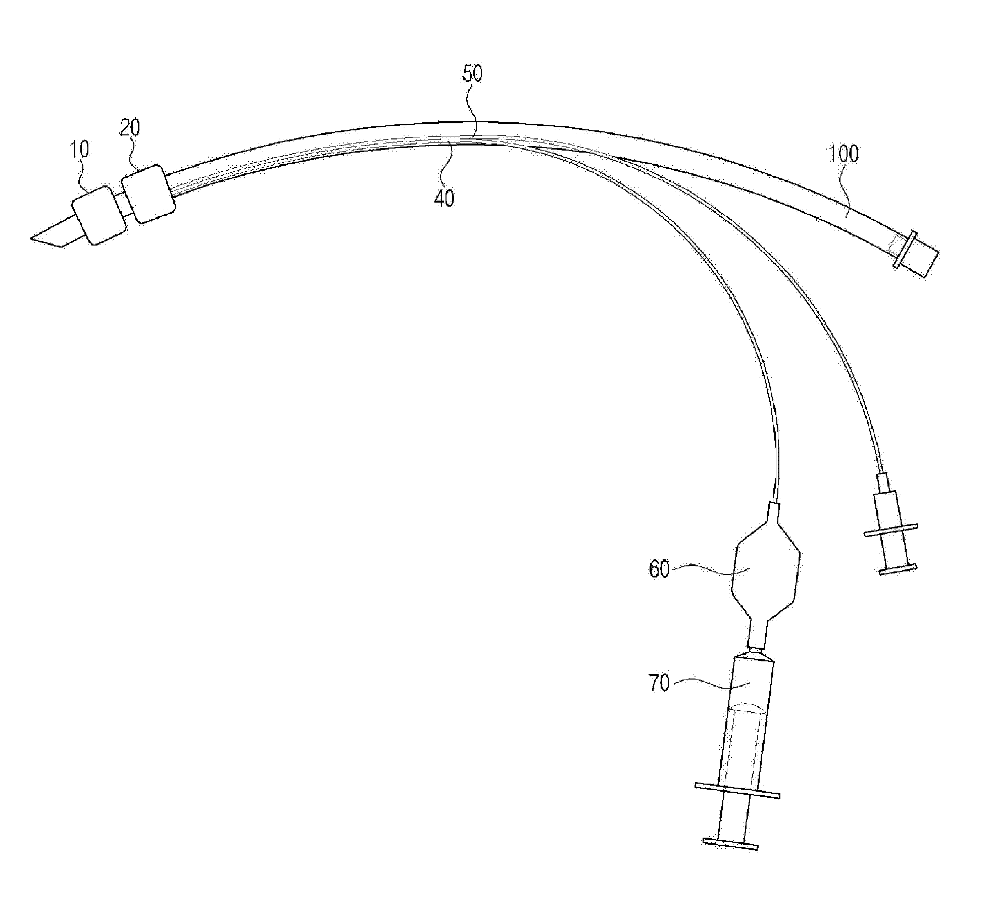
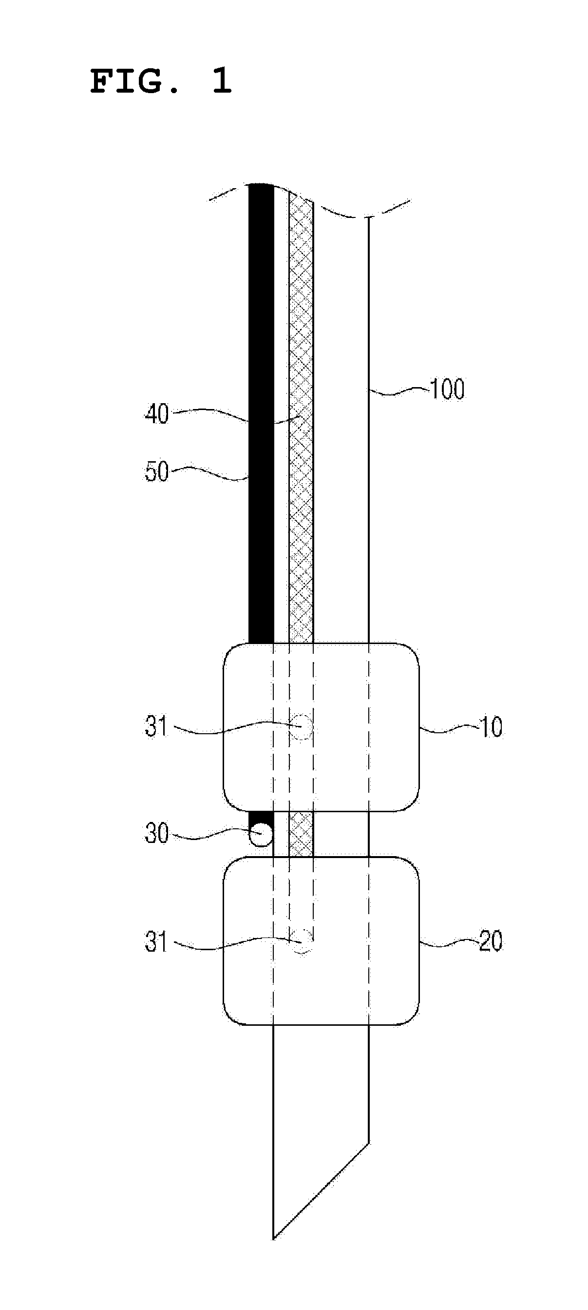
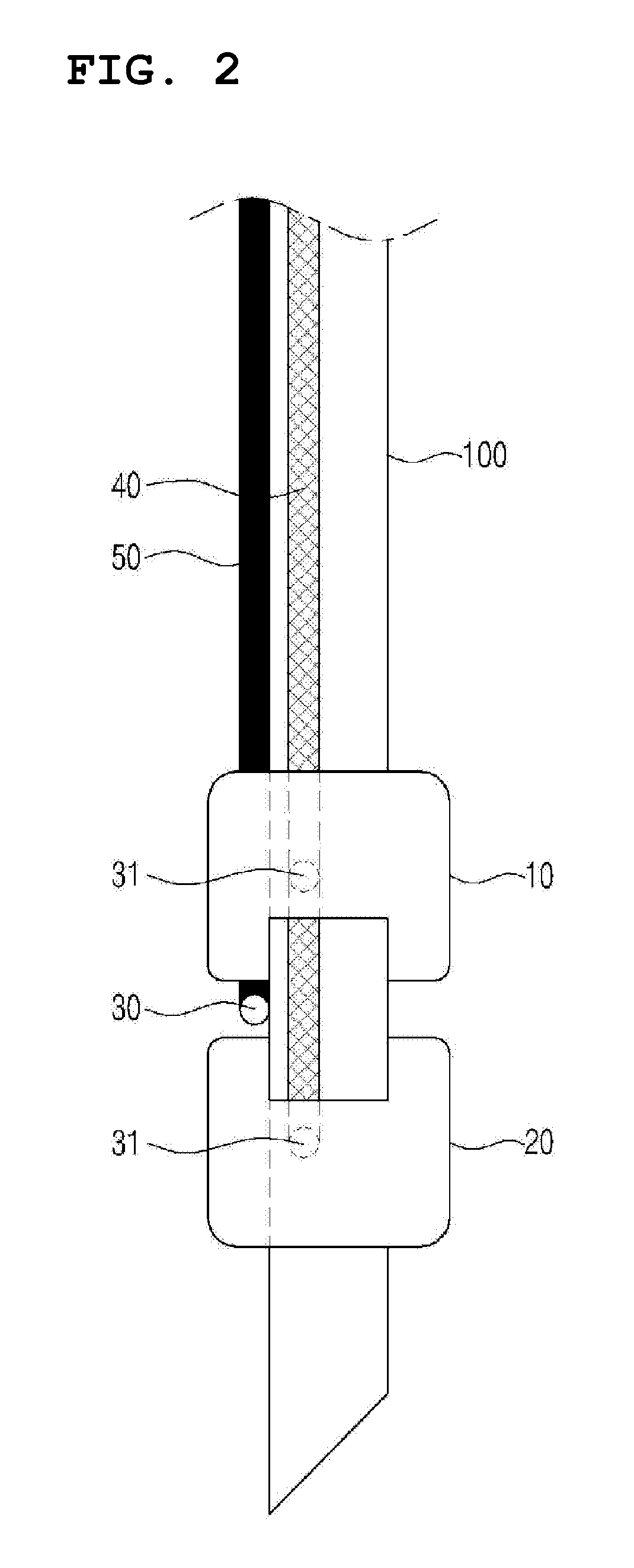
[0076]As shown in FIGS. 1 and 2, a tracheal tube according to the present invention includes a hollow tube 100 inserted into the trachea; a first volume inflator 10 surrounding one side of the hollow tube 100; a second volume inflator 20 positioned under the first volume inflator 10; a first conduit 40 adapted to inflate the first and second volume inflators 10 and 20; and a second conduit 50 adapted to supply a trachea sealing portion, which is positioned between the first and second volume inflators 10 and 20, with a sealing medium 80.

[0077]Although the second conduit 50 is shown in FIGS. 1 and 2 outside the hollow tube 100, the position is not limited thereto, and it may be positioned in a section of the hollow tube 100 or inside the hollow tube 100. If the second conduit 50 is positioned in a section of the hollow tube 100 or inside the hollow tube 100, a sealing medium passage hole 30 may be formed through the trachea sealing portion (FIG. 5).

[0078]...

embodiment 2

Function of Tracheal Tube

[0091]A tracheal tube according to the present invention is inserted into a model trachea that simulates a patient's larynx. The volume of dual volume inflators (cuffs) is inflated by using the volume controller, and the trachea sealing portion is supplied with a sealing medium 80. When the dual volume inflators are inflated to have a pressure of 20 cmH2O, and the trachea sealing portion, which is formed between them, is provided with gel (VIASYS, Madison, Wis., USA) until the pressure of the double volume inflators reaches 25 cmH2O (average volume of 2.4 ml), all of conventional tubes (Standard endotracheal tube° Euromedical, Malaysia; Safety-Flex™, Mallinckrodt, Athlone, Ireland) result in leakage within one minute, but none of the five tracheal tubes according to the present invention result in leakage even after two weeks. Pressure applied to the model trachea during this period is in the range of 7-20 cmH2O, which is not high enough to damage the trache...


PUM


Abstract

The present invention provides a tracheal tube comprising: a hollow tube inserted into the trachea; a first volume expansion portion for encompassing one side of the hollow tube; a second volume expansion portion positioned below the first volume expansion portion; a first conduit for expanding the first volume expansion portion and the second volume expansion portion; and a second conduit for supplying media for sealing to a trachea sealing portion positioned between the first volume expansion portion and the second volume expansion portion. The tracheal tube of the present invention can reduce the pressure of two cuffs which are the volume expansion portions, and can effectively improve sealing by supplying media to the trachea sealing portion positioned between the two cuffs. The tracheal tube of the present invention can reduce pulmonary aspiration and can thus considerably prevent ventilator-associated pneumonia (VAP).

Description

CROSS-REFERENCE TO RELATED APPLICATION[0001]This is a continuation of International Application No. PCT / KR2011 / 001096 filed on Feb. 18, 2011, which claims the priority to Korean Application No. 10-2010-0015402 filed Feb. 19, 2010, which applications are incorporated herein be reference.TECHNICAL FIELD[0002]The present invention relates to a tracheal tube including a trachea sealing portion and a method for manufacturing the same.BACKGROUND ART[0003]Treatment of a patient in need of mechanical ventilation frequently requires that an endotracheal tube be inserted into the trachea through the patient's mouth or nose and connected to a ventilator, which mechanically delivers air into the lungs through the tube periodically. An inflatable cuff is provided on an end of the tube and is configured to contact the inner wall of the trachea when inflated.[0004]Such a use of an endotracheal tube, however, causes a number of problems in connection with secretions that gradually pass between the ...

Claims


Application Information

Patent Timeline
Patent Type & Authority Applications(United States)
IPC IPC(8): A61M16/04
CPCA61M16/04A61M16/0486A61M16/0479A61M16/0459
Inventor KIM, JIN HEE
Owner SEOUL NAT UNIV BUNDANG HOSPITAL
Why Eureka
Try Eureka