Electric vehicle charging station and charge receiving arrangement for a vehicle

Inactive Publication Date: 2012-11-08
SYLVAN ASCENT
View PDF8 Cites 41 Cited by
  • Summary
  • Abstract
  • Description
  • Claims
  • Application Information

AI Technical Summary

Benefits of technology

[0034]The invention is advantageous in that it provides a larger target area for contact between the charging elements and the charge receiving members. This allows a driver to approach a charging station so that when the vehicle moves into position the driver has some leeway in positioning the vehicle and there does not need to be precise alignment of charging elements and charge receiving members. The structural arrangement of longitudinally arranged conducting elements provides for a large target area along the

Problems solved by technology

The fact that the metal plate is positioned in a road means that the plate could be contaminated by dirt or oil, which can reduce the effectiveness of charging because of poor electrical contact.
Further, the fact that the plate is embedded in the road means that there are difficulties in operation if the road needs to be resurfaced because the plate will need to be removed, which means that the charging station would not be operational

Method used


Image

  • Electric vehicle charging station and charge receiving arrangement for a vehicle
  • Electric vehicle charging station and charge receiving arrangement for a vehicle
  • Electric vehicle charging station and charge receiving arrangement for a vehicle

Examples


Embodiment Construction

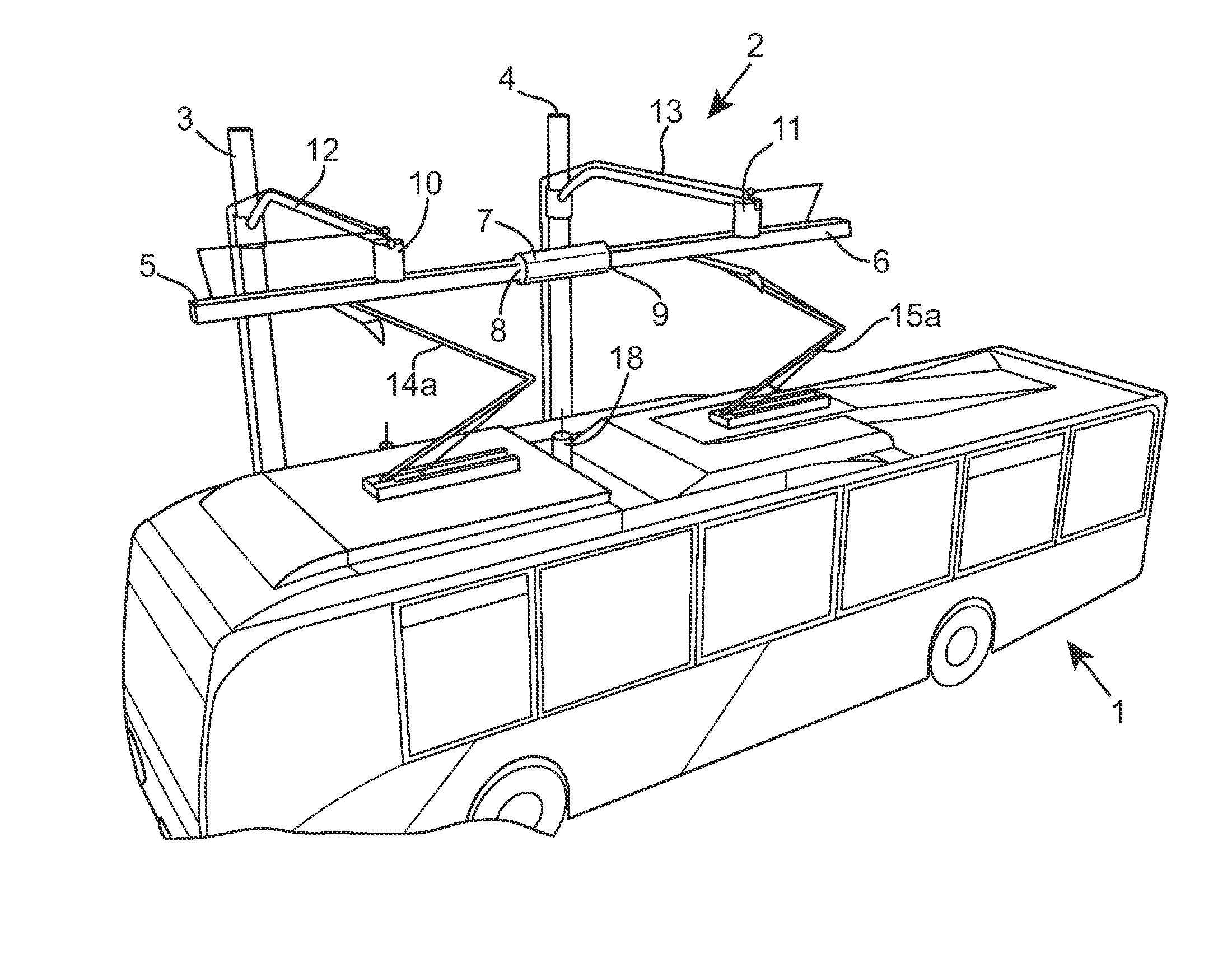
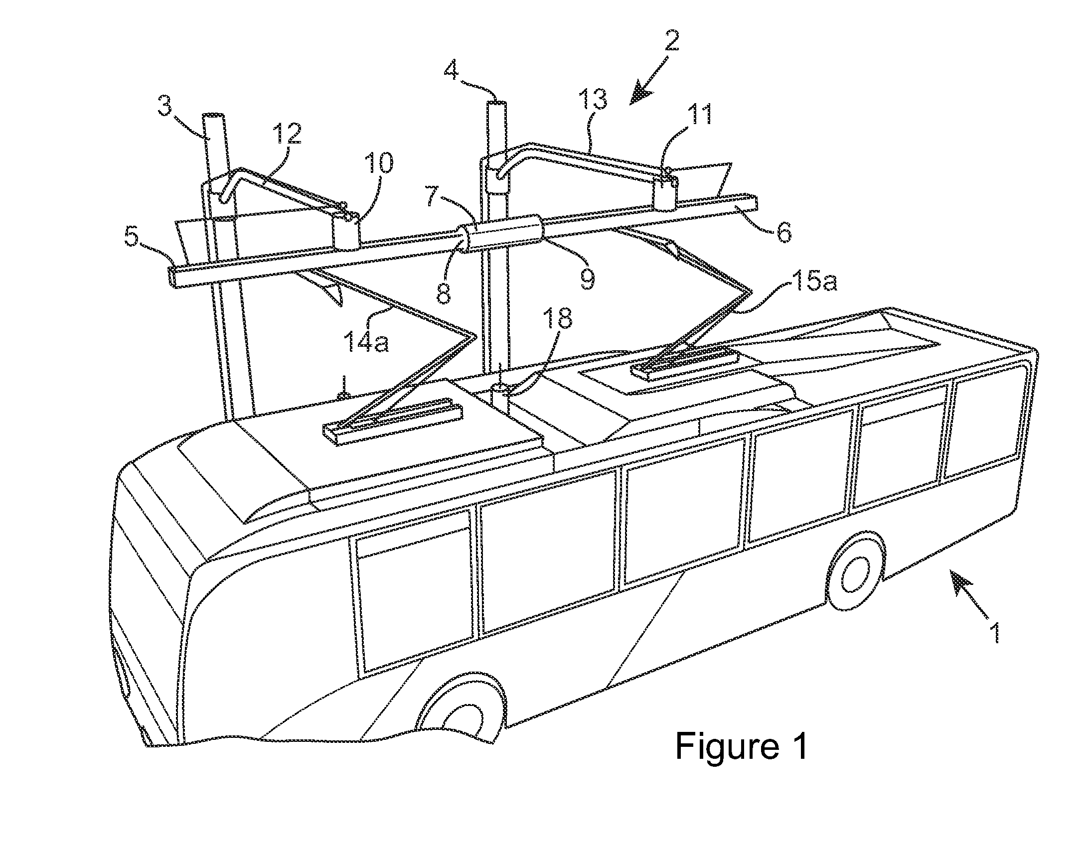
[0040]Referring firstly to FIG. 1, a bus is indicated at 1. The bus has pulled up alongside a charging station generally shown as 2. The charging station comprises two upright supports 3 and 4, each of which holds a charging element 5 and 6, which are positioned such that when the bus is in position, the charging elements are positioned along the longitudinal axis of the bus above the roof-line of the bus. The charging elements are separated by an insulating element 7, which separates the ends 8 and 9 of respective charging elements. The charging elements 5 and 6 connected to the upright supports by arms 12, 13 at an angle to the supports and there are insulators 10, 11 between the elements 5, 6 and the arms. The charging elements sit above the bus and can be moved so they come into contact with charge receiving members 14a, 15a which are attached to the top of the bus. The charging elements can be swung out horizontally from the curb although they may be in a fixed position. The ch...


PUM


Abstract

A charging station for a vehicle having supports (3 and 4), each of which holds a charging element (5 and 6), which are positioned such that when the bus is in position, the charging elements are positioned along the longitudinal axis of the vehicle and can connect with charge receiving members on the vehicle, which are similarly spaced along the longitudinal axis of the vehicle.

Description

[0001]The present invention relates to an electric vehicle charging station for charging an energy storage device of a vehicle and particularly, but not exclusively, for charging the batteries of a passenger vehicle such as a bus, trolley-bus or tram. According to a further aspect, the invention relates to a charge receiving arrangement for a vehicle, which can operate with a vehicle charging station.BACKGROUND TO THE INVENTION[0002]At present, vehicles, such as electric vehicles have energy storage devices, for example, batteries, or super-capacitors which are recharged periodically by way of charging stations that the vehicle travels to so it can be hooked or connected to a power source such as the mains electricity supply. Some vehicles may operate using an electro-mechanical device such as an energy storage flywheel and again, the vehicle travels to a charging station and is attached to the charging station so that the energy storage device is re-charged from an electrical suppl...

Claims


Application Information

Patent Timeline
IPC IPC(8): H02J7/00
CPCB60L3/0069B60L5/42B60L9/00B60L11/1837B60L2200/18B60L2240/36Y02T90/121B60M7/003Y02T10/7005Y02T90/128Y02T90/14B60L2200/26B60L2250/10Y02T10/7072B60L53/32B60L50/53Y02T10/70Y02T90/12H02J7/0027B60L53/00B60L53/14B60L53/30B60L5/18
Inventor BEDELL, ROGER
Owner SYLVAN ASCENT
Why Eureka
Try Eureka