Duodenoscope needle

a duodenoscope and needle technology, applied in the field of surgical devices, can solve the problems of increased bleeding, increased complications, and increased complications, and achieve the effects of reducing internal kinetic friction, reducing bleeding, and increasing needle control and range of movemen

Active Publication Date: 2010-06-01
US ENDOSCOPY GROUP
View PDF19 Cites 1 Cited by
  • Summary
  • Abstract
  • Description
  • Claims
  • Application Information

AI Technical Summary

Benefits of technology

[0019]The present invention offers advantages over devices available in the prior art. The device offers low internal kinetic friction allowing ease of needle extension and retraction while the distal end of the scope is bent at acute angles. The device further offers the surgeon increased needle control and range of movement outside of the endoscope. The increased range of needle movement increases available target areas within the subject, while at the same time, decreasing procedural performance time. In addition, the device also features precise, repeatable and safe operational features in regard to the length of the device.

Problems solved by technology

In some cases, the bile duct can become blocked.
This condition causes jaundice and can lead to further complications.
Although this procedure typically is successful in opening the valve sufficiently for bile flow, excessive bleeding is a common and dangerous complication with this and other similar procedures.
Procedures for treating the bile duct blockage, as well as treating subsequent bleeding caused by the procedures, have been limited by the relative inaccessibility of the valve.
The outlet port of the bile duct is located at an undesirable angle, making access difficult by conventional endoscopic injection therapy techniques.
Although surgeons in most cases can maneuver a scope into a desired position, extending the needle in order to inject the chemical agent is made prohibitively difficult by the bile duct location.
Using conventional injection therapy devices within a scope, surgeons experience difficulty in extending needles prior to injecting the chemical agent.
Even if a surgeon can successfully extend the needle, there is an equal difficulty in retracting the needle after injection of the chemical agent.
This undesirable condition can cause injure to the patient.
This technique is not without failure.

Method used


Image

  • Duodenoscope needle
  • Duodenoscope needle
  • Duodenoscope needle

Examples


Embodiment Construction

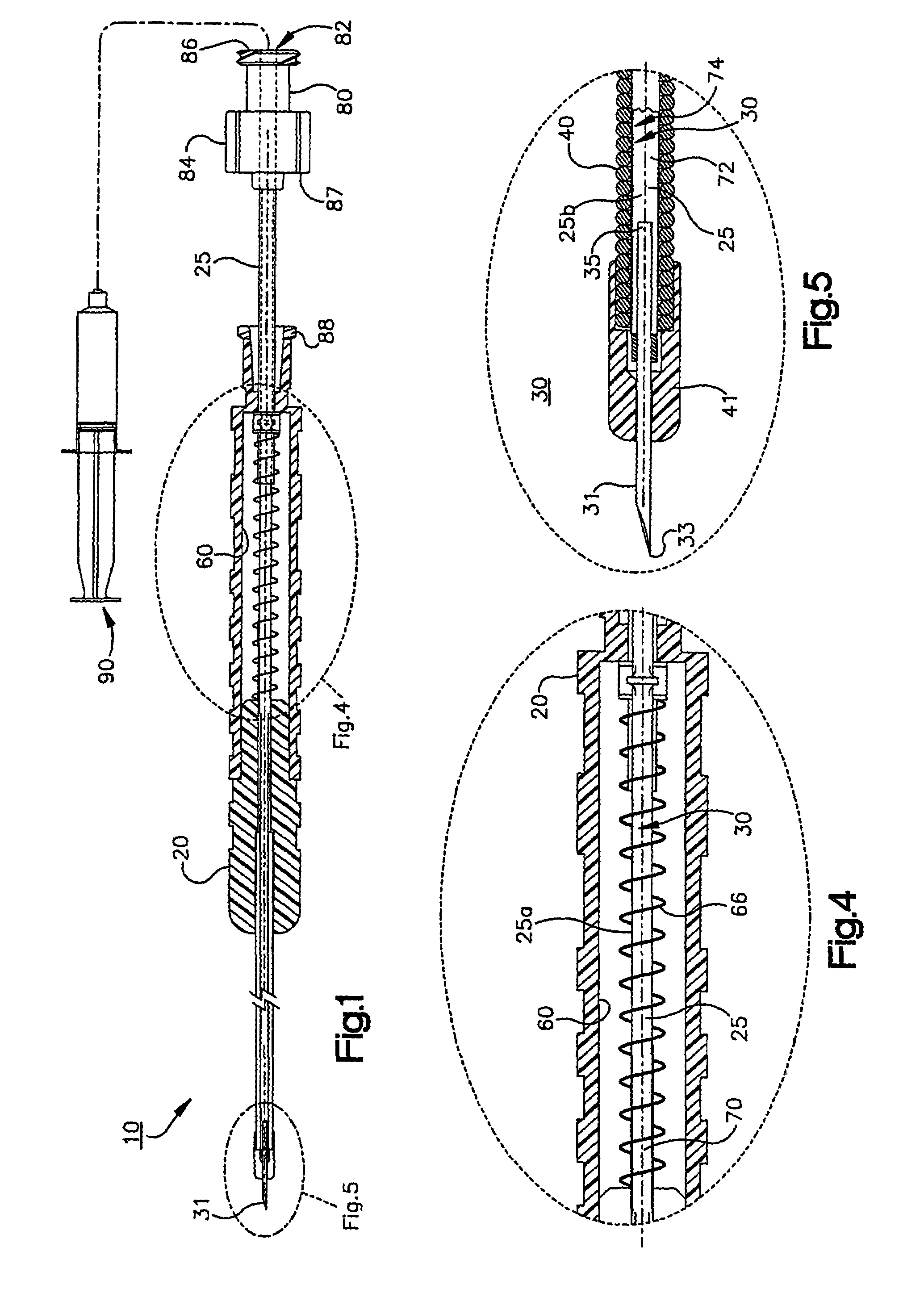
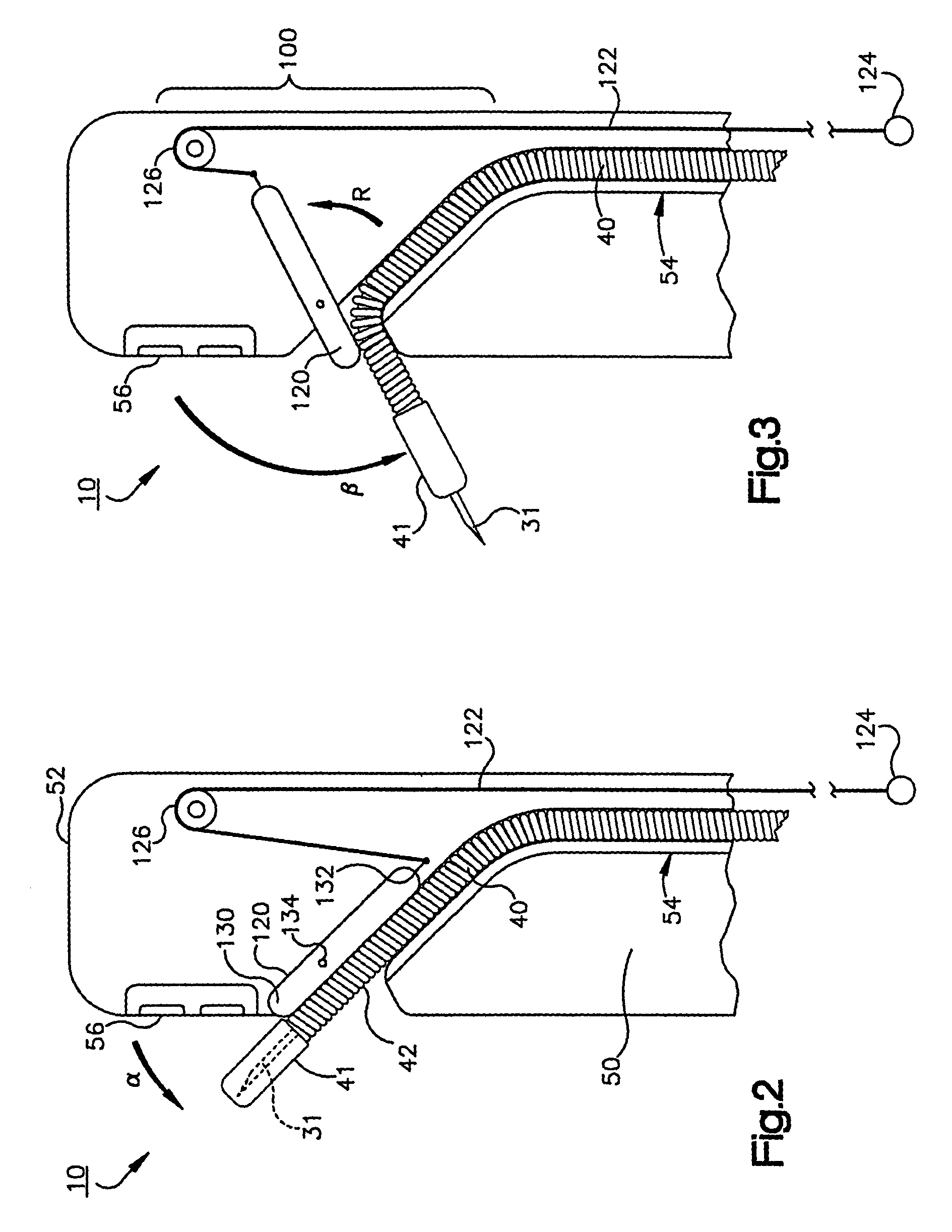
[0033]A surgical device 10 for injecting a chemical agent into a subject for use in endoscopic injection therapies is illustrated by the drawings. Referring to FIGS. 1 and 2, the device 10 comprises a support body 20, a motion transmitting unit 25, an agent delivery system 30 and a guide housing 40.

[0034]The device 10 is so constructed and arranged that it may be inserted into a proximal end of an endoscope, or similar device. The agent delivery system 30 and guide housing 40 are further constructed and arranged so that they may be controlled by a surgeon during operation of an endoscopic device. The present invention advantageously allows the surgeon to inject a chemical agent into a human subject at a precise, desirable location. The chemical agent is injected into the subject via a needle 31 located at the distal end of the device 10. While the needle is safely recessed into the device, the surgeon can manipulate the needle into the desired position. The device 10 offers new and ...


PUM


Abstract

A surgical device for injecting a chemical agent within a subject for use in endoscopic injection therapies is disclosed. The device includes a support body, a motion transmitting unit, an agent delivery system and a guide housing. The motion transmitting unit is movable relative to the support body. The agent delivery system includes a needle for extending into a subject and structure defining a conduit between the support body and the needle. The guide housing has a flexible elongated body, an internal elongated passage and friction reducing material lining the passage. At least a portion of the motion transmitting unit adjacent the needle is slideably housed within the guide housing. The device offers a surgeon improved ease of needle extension and retraction when the distal end of the endoscope is bent at acute angles.

Description

CROSS REFERENCE TO RELATED APPLICATIONS[0001]The present application is a divisional application of U.S. patent application Ser. No 10 / 146,525, filed May 15, 2002, now U.S. Pat. No. 6,666,847 which is turn claims benefit of U.S. provisional application Ser. No. 60 / 292,169, entitled “Duodenoscope Neddle,” filed on May 18, 2001.FIELD OF THE INVENTION[0002]The present-invention relates to surgical devices and more particularly to surgical devices constructed for endoscopic injection therapy.BACKGROUND OF THE INVENTION[0003]Endoscopic injection therapy was first used to stop certain types of internal bleeding as early as 1939. This therapy method involves the injection of a chemical agent through a needle injector into or around a bleeding site within the human body to stop excessive bleeding. A variety of other applications for endoscopic injections have been developed, including biliary duct treatments.[0004]Bile is a bitter yellow or greenish liquid that is secreted by the liver into...

Claims


Application Information

Patent Timeline
Patent Type & Authority Patents(United States)
IPC IPC(8): A61M5/178A61B1/00A61B1/018A61B17/12A61B17/28A61B17/34A61M5/14A61M25/00A61M25/01
CPCA61B1/00098A61B17/3478A61B1/018A61B17/12A61M2025/009A61B2017/2927A61M25/0116A61M25/0133A61M2025/0089A61B2017/2905
Inventor SECREST, DEAN J.YOUNKER, MARLIN E.GREULOCH, WILLIAM
Owner US ENDOSCOPY GROUP
Why Eureka
Try Eureka