
Lens

A lens and lens technology, applied in the field of lenses, can solve the problems of reduced product adaptability, the inability to achieve miniaturization of cameras, and the use of a large number of lenses.

Active Publication Date: 2022-03-11
ZHEJIANG DAHUA TECH CO LTD
View PDF2 Cites 2 Cited by
  • Summary
  • Abstract
  • Description
  • Claims
  • Application Information

AI Technical Summary

Problems solved by technology

However, the following problems still exist in the current optical imaging lens: 1. The existing lens has a small imaging target surface size and low resolution of the collected image
2. The lens aperture is small, and the camera image is very dark under low illumination conditions, which reduces the adaptability of the product
3. The number of lenses used is large, and the size of the lens is large, so that the entire camera cannot be miniaturized.
4. The resolution of the lens is not high, and the image quality is average
5. Most lenses do not have infrared confocal function

Method used


Image

  • Lens
  • Lens
  • Lens

Examples


Embodiment 1

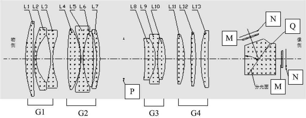
[0084] In the specific implementation process, the curvature radius R, central thickness Tc, refractive index Nd, Abbe constant Vd and conic coefficient k of each lens of the lens meet the conditions listed in Table 1:

[0085]

[0086]

[0087] Table 1

[0088] It should be noted that the mirror serial numbers in Table 1 are figure 1 In the schematic diagram of the lens structure shown, the surface numbers of the lenses from left to right;

[0089] The lens provided by the embodiment of the present invention has the following optical technical indicators:

[0090] Optical total length TTL≤120mm;

[0091] Lens focal length f: 16mm;

[0092] Field of view of the lens: 61°;

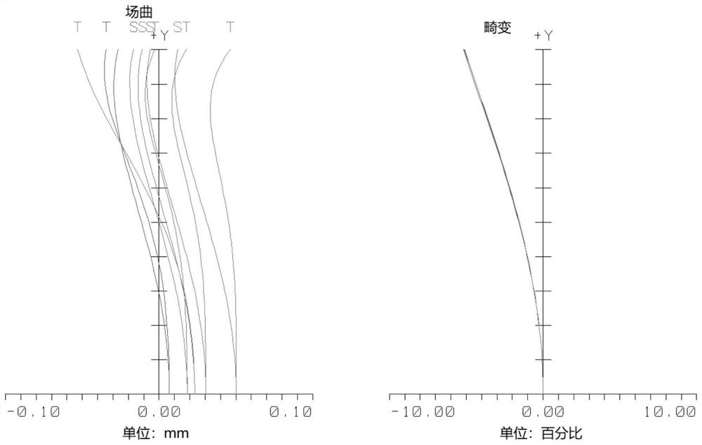
[0093] Optical distortion of the lens: -5.1%;

[0094] The aperture FNO. of the lens system: 1.3;

[0095] Lens image size: 1.1".

Embodiment 2

[0097] In the specific implementation process, the curvature radius R, central thickness Tc, refractive index Nd, Abbe constant Vd and conic coefficient k of each lens of the lens meet the conditions listed in Table 2:

[0098]

[0099]

[0100] Table 2

[0101] It should be noted that the mirror serial numbers in Table 2 are figure 1 In the schematic diagram of the lens structure shown, the surface numbers of the lenses from left to right;

[0102] The lens provided by the embodiment of the present invention has the following optical technical indicators:

[0103] Optical total length TTL≤120mm;

[0104] Lens focal length f: 16.5mm;

[0105] Field of view of the lens: 55°;

[0106] Optical distortion of the lens: -4.5%;

[0107] The aperture FNO. of the lens system: 1.2;

[0108] Lens image size: 1.1".

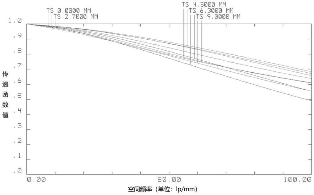
[0109] The lens provided by this embodiment will be further introduced below by analyzing the optical system of the embodiment in detail.

[0110] The optical t...


PUM

PropertyMeasurementUnit
Optical lengthaaaaaaaaaa

Abstract

The invention discloses a lens which is formed by sequentially arranging a first lens group, a second lens group, an aperture diaphragm, a third lens group, a fourth lens group and a light splitting device from an object side to an image side. Each light emitting side of the light splitting device sequentially comprises an optical filter and an image surface; the lens satisfies the following conditions: fG2 is the focal length of the third lens group, f is the system focal length of the lens, and FOV is the field angle of the lens. Four lens groups are sequentially arranged in the lens from the object side to the image side according to a specific sequence, the four lens groups comprise 13 lenses with specific focal power, and the lens meets the requirement that the optical lens which is high in resolution, large in target surface, large in aperture, small in size and low in cost is achieved.

Description

technical field [0001] The invention relates to the technical field of optical imaging, in particular to a lens. Background technique [0002] Thanks to the rapid development in the field of security monitoring in recent years, optical lenses have been used more and more in the field of security, especially in the fields of intelligent buildings and intelligent transportation, where the pixel requirements of optical imaging lenses are getting higher and higher. At the same time, thanks to the increasingly mature use of the dual-COMS technology platform, the lens is also developing towards the direction of dual optical paths. [0003] With the rapid development of the security field, fixed-focus lenses have more stable optical performance than zoom lenses, and their demand is also the highest. However, the following problems still exist in the current optical imaging lens: 1. The existing lens has a small imaging target surface and low resolution of the collected image. 2. ...

Claims


Application Information

Patent Timeline
IPC IPC(8): G02B13/00G02B13/14
CPCG02B13/00G02B13/146
Inventor 邢圆圆刘凯郭安峰
Owner ZHEJIANG DAHUA TECH CO LTD
Learn More