
Method and System for Backlight Control Using Statistical Attributes of Image Data Blocks

Inactive Publication Date: 2012-11-08
DOLBY LAB LICENSING CORP
View PDF17 Cites 58 Cited by
  • Summary
  • Abstract
  • Description
  • Claims
  • Application Information

AI Technical Summary

Benefits of technology

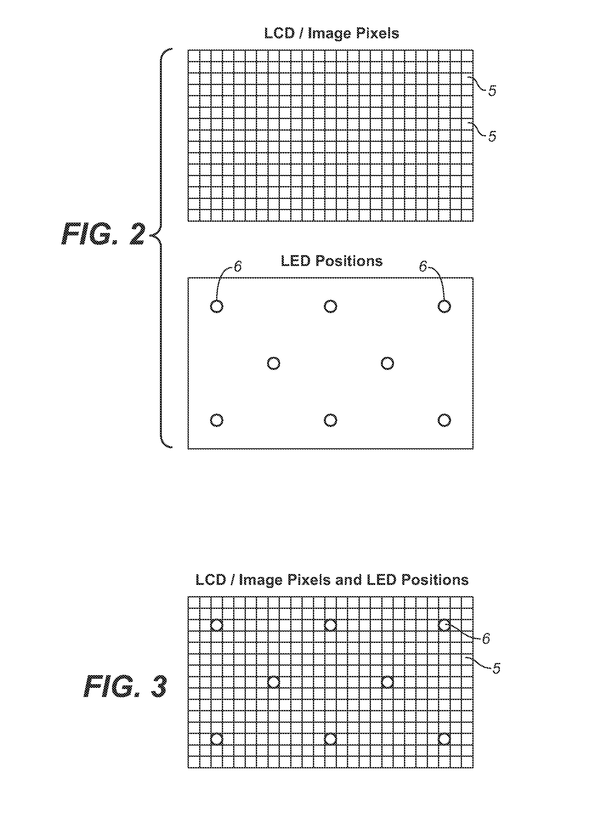
[0024]The resolution of each downsampled image is closely related (e.g., identical, in some cases) to the resolution of the backlight panel. For example, if the backlight elements are arranged as a rectangular grid (e.g., a rectangular array of LED cells), the downsampled image resolution can be equal to the backlight grid resolution or a multiple of the backlight grid resolution (i.e., N times the backlight grid resolution, where N is an integer). If the backlight grid is arranged other than as a rectangular grid (e.g., as a hexagonal array of backlight elements), the spatial locations of the pixels of the downsampled image can correspond to the minimal (lowest resolution) rectangular grid that contains all the backlight element positions. Such a minimal rectangular grid allows for easier and more efficient implementation of the inventive system and method.
[0025]Preferred embodiments of the invention determine at least two statistical attributes (e.g., mean and standard deviation) of blocks of image data (input image data or image data derived from input image data) in an efficient manner, and use them to determine backlight drive values. In preferred embodiments, the statistical measures are determined from input image data at a relatively low resolution equal to the resolution of a downsampled version of each input image. Preferably, at least one statistical attribute is determined for each pixel subset of a number of pixel subsets (blocks) of a full resolution image (an input image or full resolution image derived from an input image) by a method including at least one nonlinear operation on data indicative of (e.g., derived from) the pixel subset. Herein, including in the claims, the expression “nonlinear operation” on data values is intended to exclude the operation of determining a subset (e.g., one) of the values that satisfies a predetermined criterion (e.g., it is not intended to denote an operation of determining a maximum or minimum one of the values, or an operation of determining which of the values exceed a predetermined threshold value). An example of the nonlinear operation performed in some preferred embodiments of the inventive method is an operation of squaring image data values, and the method (in these embodiments) may generate a standard deviation value for each of a number of pixel subsets of a full resolution image. For each of the statistical attributes determined in preferred embodiments of the invention, a low resolution “image” (a downsampled image) consisting of values of the statistical attribute (or values derived from such values) is determined from each full resolution image. The backlight drive values are determined from the low resolution images in order to achieve stable backlight and to reduce or prevent artifacts (e.g., translating halo artifacts) that would result during full resolution image display using conventional backlight control (e.g., conventional backlight control that does not include an nonlinear operation of the described type). Backlight drive values determined in accordance with preferred embodiments cause the display to produce stable backlight and also reduce or eliminate such artifacts. In some preferred embodiments, backlight drive values are determined from a downsampled image consisting of values each equal to a linear combination of the standard deviation and mean of a different compact subset of pixels of an image to be displayed, where this downsampled image is determined from two other downsampled images: one consisting of the standard deviation of each of the compact subsets of pixels; the other consisting of the mean of each of the compact subsets of pixels.
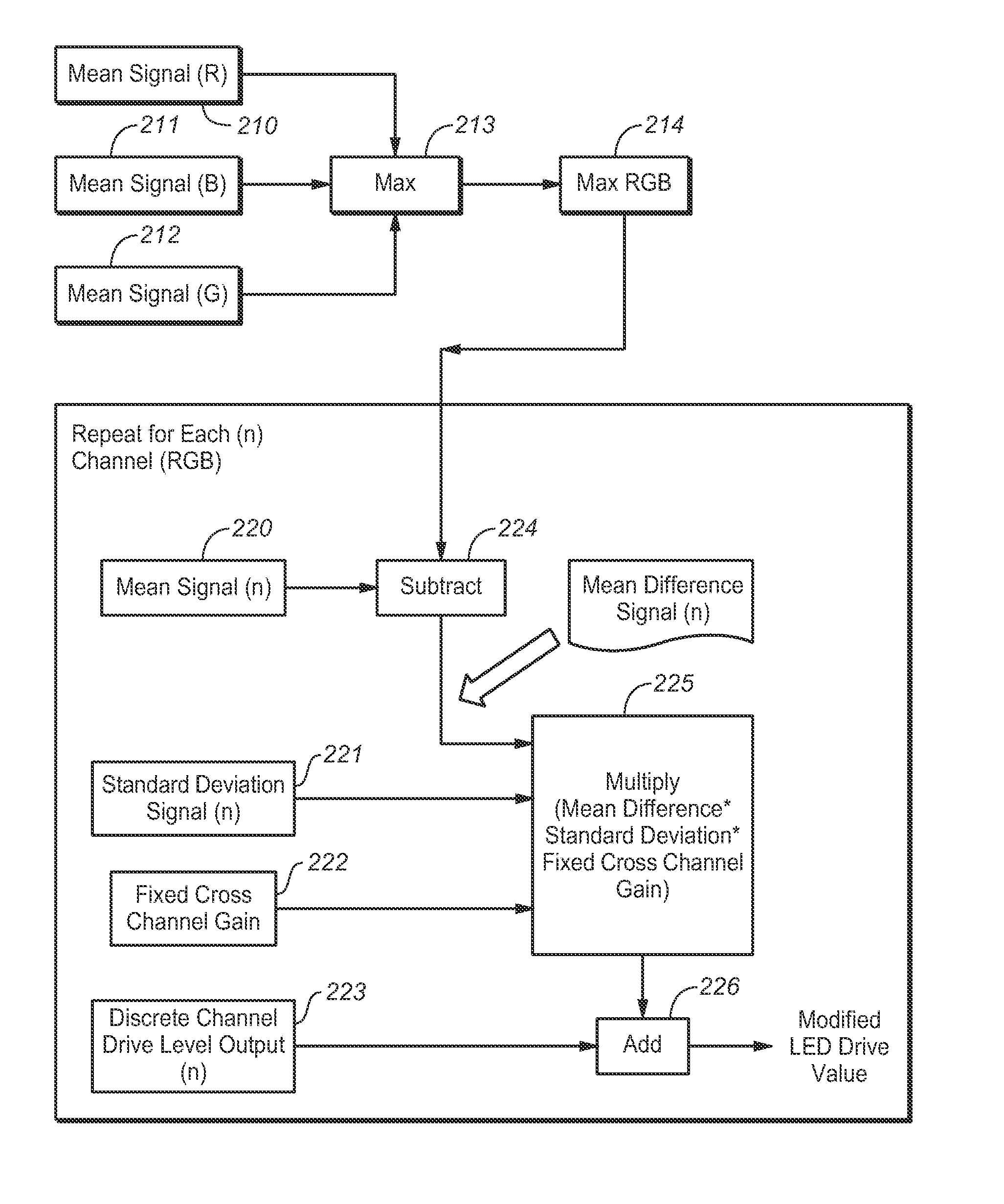
[0028]In a second class of embodiments of the inventive method and system, a set of backlight control values is determined for each color channel of each backlight element (cell) of a backlight panel of a dual modulation display (e.g., for each of red, green, and blue channels of each backlight element of a backlight array). In typical embodiments in this class, a set of backlight control values is generated independently for each color channel of the backlight panel, and a cross-channel correction operation is performed on these sets of backlight control values to determine a modified set of backlight control values for each color channel. Embodiments in the second class can improve both the achievable color gamut and overall system efficiency (relative to the color gamut and system efficiency achievable by the above-described first class of embodiments).
[0030]In preferred embodiments in both the first class and the second class, a bandlimiting filter (e.g., a low pass filter) is applied to a downsampled image (or to each of a number of downsampled images) generated during generation of backlight control values to remove high frequencies in the downsampled image. Failure to so filter a downsampled image could result in aliasing (due to the downsampling step) that could cause visual artifacts in the displayed image. An important advantage of applying the bandlimiting filter(s) to relatively low resolution data (the downsampled image) rather than to higher resolution data (e.g., full resolution input image data) is that this allows the filter(s) to be simple and inexpensive to implement.
[0037]In some embodiments in the third class, steps (a) and (b) are performed by single pass data processing (without feedback). In response to the backlight drive values produced in typical embodiments in the third class, the backlight panel produces stable backlight.
[0044]In some embodiments in the fourth class, steps (a) and (b) are performed by single pass data processing (without feedback). In response to the backlight drive values produced in typical embodiments in the fourth class, the backlight panel produces a stable backlight.

Problems solved by technology

High contrast ratios are desirable for accurate image reproduction, but are often limited in traditional displays.
If an input image contains pixel values beyond the contrast range of an LCD panel, the backlight will not be optimal for all LCD pixels.
Typically the choice of backlighting level for a local area of an LCD panel is not optimal for all LCD pixels in the area.
For some LCD pixels the backlight might be too high, while for others the backlight might be too low.
If backlighting is too high, accurate low levels including black are compromised.
These clipping and contouring artifacts may occur in traditional constant backlit LCD displays.
Perceptually (to many viewers), white clipping artifacts are more objectionable than black contouring and clipping.
Motion video (display of a changing sequence of images) adds additional problems.
For clipping and contouring artifacts, this results in changes in both the actual pixels that clip and contour, and the brightness of affected pixels.
If halos are present, a changing backlight results in changing halos.
Backlight levels above 100% are inefficient because they may be blocked by the LCD layer.
The method described in U.S. Pat. No. 7,505,027 for determining individual backlight settings is impractical and limited for a number of reasons including the following.
The method would not achieve good display quality or adequately reduce artifacts when displaying a sequence of input images indicative of at least one moving bright object (e.g., a cursor or other bright object translating across the display screen).
In this case, the method would typically produce a translating halo artifact having the appearance of a displayed halo (excessively backlit area) surrounding each bright moving object as the object moves across the display screen.
Also undesirably, the low pass filtering performed by the method of U.S. Pat. No. 7,505,027 is performed on the full set of luminance values of the input image rather than on a reduced set of image data values (e.g., luminance values of a downsampled version of each input image).
Thus, the low-pass filtering operation of U.S. Pat. No. 7,505,027 is complicated and expensive to implement.
In general, conventional methods for determining individual backlight settings for a dual modulation display undesirable cause image artifacts and are complicated and expensive to implement.

Method used


Image

  • Method and System for Backlight Control Using Statistical Attributes of Image Data Blocks
  • Method and System for Backlight Control Using Statistical Attributes of Image Data Blocks
  • Method and System for Backlight Control Using Statistical Attributes of Image Data Blocks

Examples


Embodiment Construction

[0065]Many embodiments of the present invention are technologically possible. It will be apparent to those of ordinary skill in the art from the present disclosure how to implement them. Embodiments of the inventive system and method will be described with reference to FIGS. 1 and 9-12.

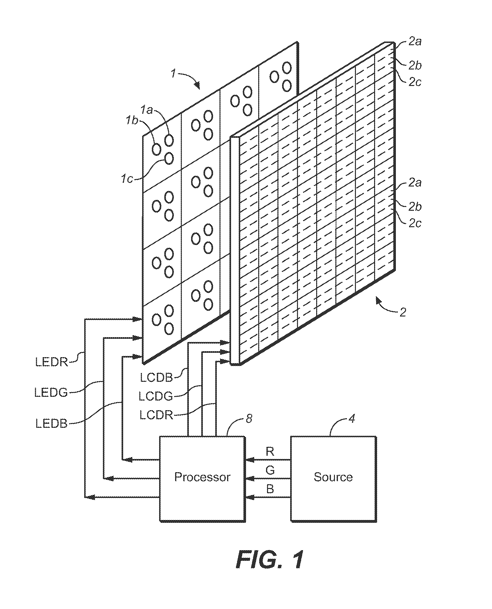
[0066]FIG. 1 is a block diagram of an embodiment of the inventive system. The system of FIG. 1 includes a dual modulation display for displaying images sequentially in response to a video input signal from source 4. The display comprises front modulating panel 2 and backlight panel 1 positioned (by means not shown) behind panel 2. Optionally, a diffuser panel (not shown) is positioned between panels 1 and 2. The system also includes processor 8, coupled between the dual modulation display and source 4 and configured to generate driving signals for both panels of the display in response to the input signal.

[0067]In FIG. 1, processor 8 has outputs coupled to backlight panel 1 and to panel 2, and inputs ...


PUM


Abstract

A method and system for generating backlight control values for a dual modulation display including a front panel having a first resolution and a backlight subsystem having lower resolution than the front panel, in response to input image data. Some embodiments determine statistical data indicative of at least one statistical measure of each of a number of spatially compact subsets of pixels of image data having the first resolution, where the pixels of image data are pixels of the input image data, color components of pixels of the input image data, or data values derived from pixels of the input image data. Some embodiments determine backlight drive values for each color channel of the backlight subsystem, including by determining statistical data for each color channel, determining backlight drive values for each color channel from the statistical data, and performing cross-channel correction on these backlight drive values.

Description

CROSS-REFERENCE TO RELATED APPLICATIONS[0001]This application claims priority to U.S. Patent Provisional Application No. 61 / 286,884, filed 16 Dec. 2009, hereby incorporated by reference in its entirety.BACKGROUND OF THE INVENTION[0002]1. Field of the Invention[0003]The invention relates to systems and methods for controlling backlight panels of dual modulation displays in response to input image data. Some embodiments of the inventive system and method determine at least two statistical attributes (e.g., mean and standard deviation) of each of a number of subsets (blocks) of pixels of an image and use them to determine individual settings for backlights (e.g., LED cells) of a dual modulation display, preferably to achieve an improved (e.g., maximized) displayed image contrast ratio while achieving stable backlight and reducing (e.g., minimizing) clipping, contouring, and motion artifacts, and preferably also optimizing energy efficiency.[0004]2. Background of the Invention[0005]Thro...

Claims


Application Information

Patent Timeline
IPC IPC(8): G09G3/36G09G5/10
CPCG09G3/3426G09G2320/0261G09G2330/021G09G2320/066G09G2320/0646
Inventor ORLICK, CHRISTOPHER J.SHIELDS, JEROME D.MILLER, J. SCOTT
Owner DOLBY LAB LICENSING CORP
Learn More