Method and device for antenna calibration

Active Publication Date: 2012-11-29
DATANG MOBILE COMM EQUIP CO LTD
View PDF13 Cites 5 Cited by
  • Summary
  • Abstract
  • Description
  • Claims
  • Application Information

AI Technical Summary

Benefits of technology

[0020]The foregoing solution proposed by the invention can monitor in real time a varying difference of the radio frequency channel through the calibration error parameters and inspect in real time calibration precision by reporting the calibration error parameters. Furthermore, the foregoing solution proposed by the invention can adjust in real time a calibration period according to the calibration error parameters by shortening the calibration period for a rapidly varying radio frequency channel or lengthening the calibration period for a slowly varying radio frequency channel and perform in a timely way reasonable antenna calibration in view of the calibration precision. The foregoing solution proposed by the invention makes minor modifications to an existing system without any influence on compatibility of the system and is easy and efficient to implement.

Problems solved by technology

In an existing antenna calibrating technology, a calibration period is set manually, and it is impossible to report in real time the presence of the differences of amplitudes and phases of respective radio frequency channels after the calibration.
If the differences of the amplitudes and the phases of the radio frequency channels last for a long calibration period, there may be a strong influence on downlink beamforming, particularly beamforming of a broadcast channel, thus resulting in broadcast beam distortion and failing to satisfy required beamforming of 65+ / −5 degrees for network planning.
(1) Calibration precision cannot be fed back, and therefore such a condition cannot be monitored that there is still a difference of a radio frequency channel after the calibration.
(2) The calibration period cannot be adjusted in real time according to the calibration precision by shortening the calibration period for a rapidly varying radio frequency channel or lengthening the calibration period for a slowly varying radio frequency channel.

Method used


Image

  • Method and device for antenna calibration
  • Method and device for antenna calibration
  • Method and device for antenna calibration

Examples


Embodiment Construction

[0025]The embodiments of the invention will be detailed below, and examples of the embodiments will be illustrated in the drawings throughout which identical or similar reference numerals represent identical or similar elements or elements with identical or similar functions. The embodiments to be described below with reference to the drawings are illustrative and merely intended to explain the invention but will not be construed as limiting the invention.

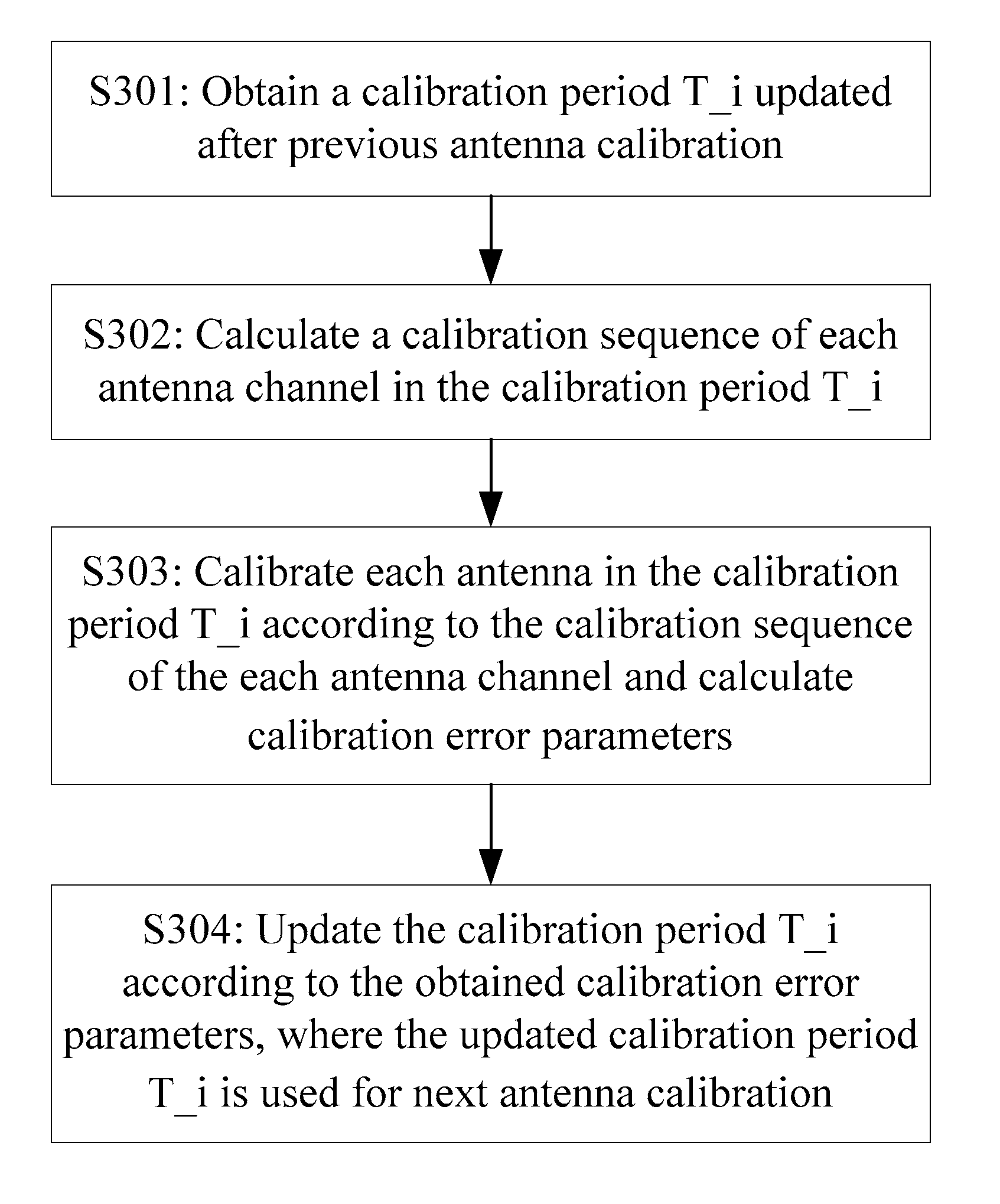
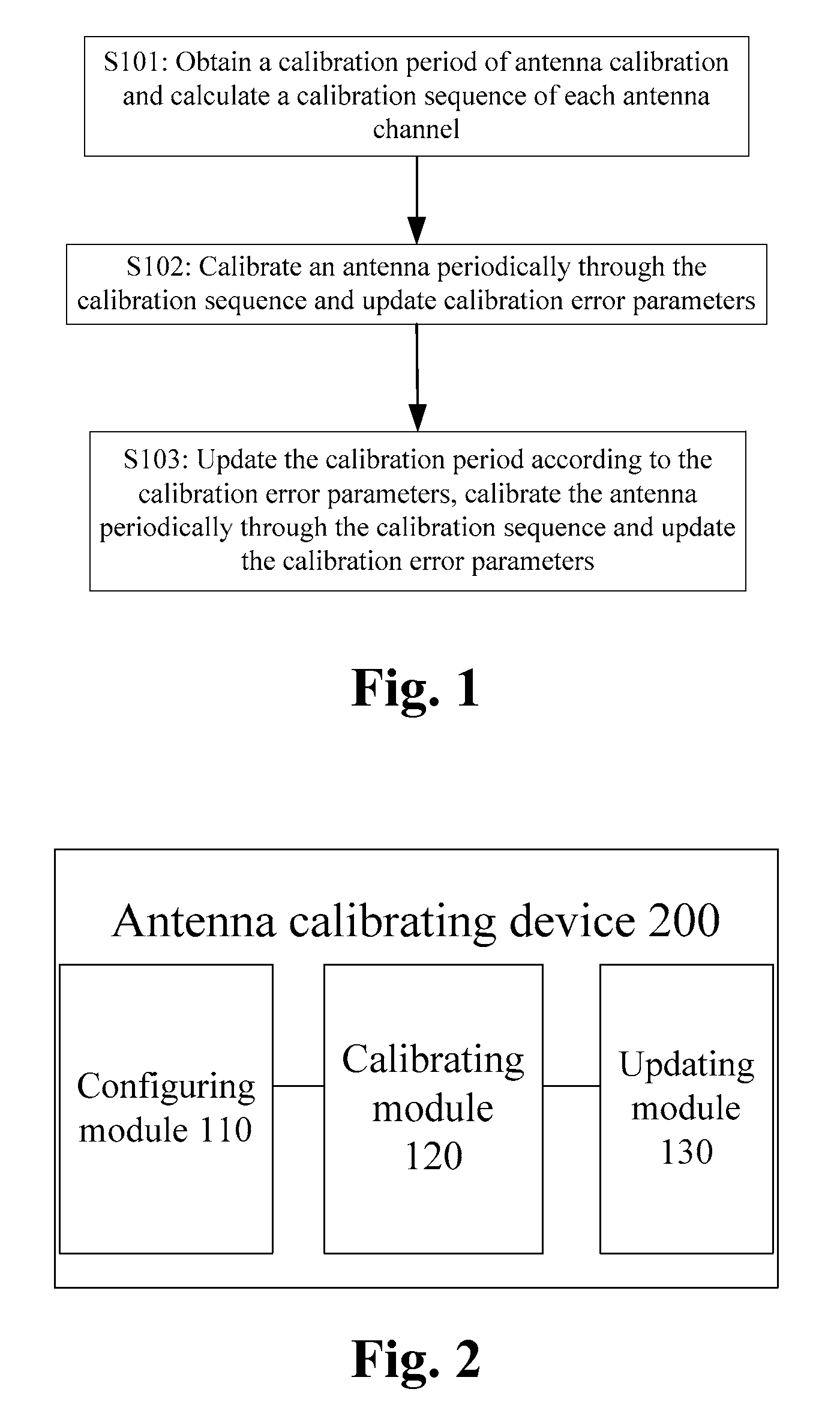
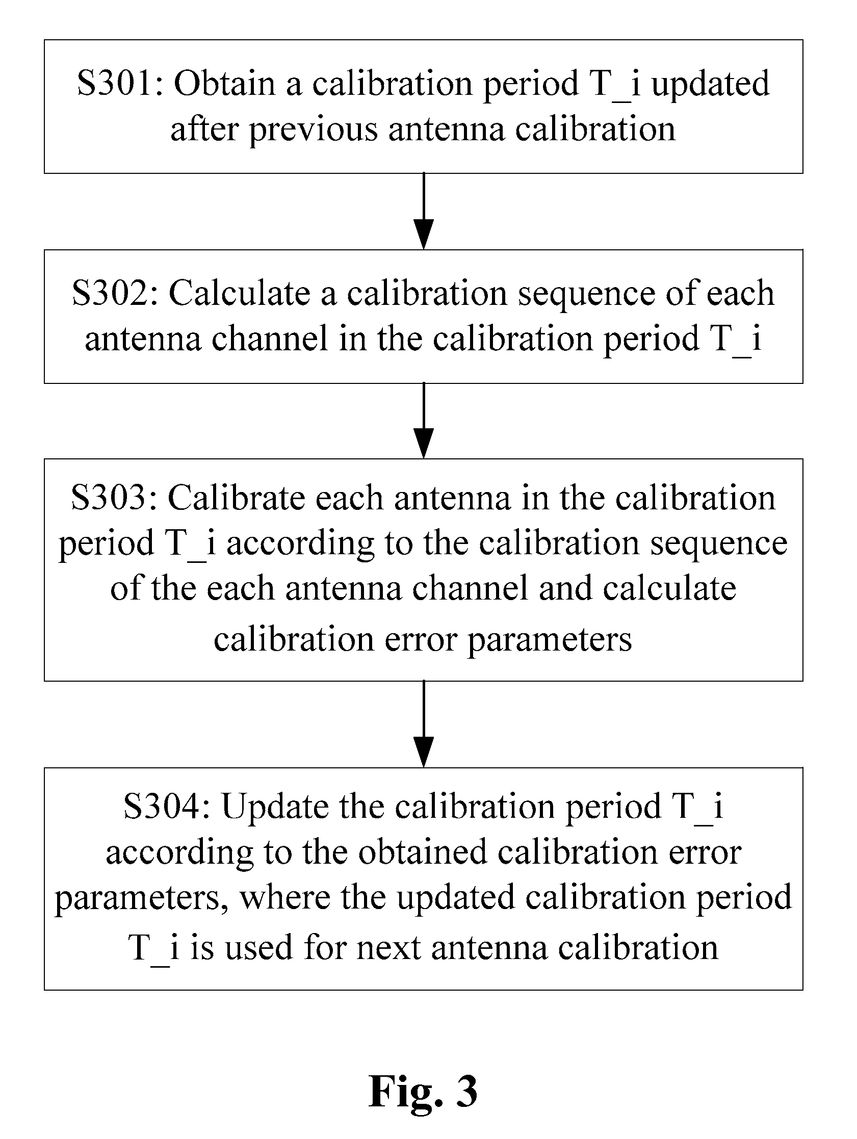
[0026]In order to achieve the object of the invention, the invention discloses an antenna calibrating method including the steps of: obtaining a calibration period T_i updated after previous antenna calibration and calculating a calibration sequence of each antenna channel in the calibration period T_i; calibrating each antenna in the calibration period T_i according to the calibration sequence of the each antenna channel and calculating calibration error parameters; and updating the calibration period T_i according to the obtained...


PUM


Abstract

A method for antenna calibration is provided, which includes the following steps: obtaining an updated calibration period T_i after the last time of antenna calibration (S301), calculating a calibration sequence of each antenna channel in the calibration period T_i (S302); according to the calibration sequence of each antenna channel, calibrating each antenna based on the calibration period T_i, and calculating a calibration error parameter (S303); and according to the obtained calibration error parameter, updating the calibration period T_i, and using the updated calibration period T_i for the next time of antenna calibration (S304). The technical solutions provided in the present invention, can monitor difference variety of radio channels in real time by the calibration error parameter, and reflect the calibration precision in real time by the reported calibration error parameter. Moreover, the technical solutions provided in the present invention, can adjust the calibration period in real time according to the calibration error parameter, and timely execute rational antenna calibration according to the calibration precision status.

Description

FIELD OF THE INVENTION[0001]The present invention relates to the field of mobile communications and particularly to an antenna calibrating method and device.BACKGROUND OF THE INVENTION[0002]Mobility and broadband has become a development trend of modern communication technologies, and how to alleviate influences of co-channel interference, multi-access interference and multi-path fading has become a predominant factor considered while improving the performance of a wireless mobile communication system. In recent years, an intelligent antenna technology has become a study hotspot in the field of mobile communications.[0003]The smart antenna technology brings a significant advantage to a mobile communication system. For example, smart antennas are used in connection with other baseband digital signal processing technologies, e.g., joint detection, interference cancellation, etc., and with the use of the smart antenna technology in a wireless base station, the base station receives a s...

Claims


Application Information

Patent Timeline
IPC IPC(8): H01Q3/22
CPCH01Q3/267
Inventor LI, CHUANJUNSUN, CHANGGUO
Owner DATANG MOBILE COMM EQUIP CO LTD
Why Eureka
Try Eureka