Light source module and backlight module

a backlight module and light source technology, applied in the direction of discharge tube main electrodes, lighting and heating apparatus, instruments, etc., can solve the problems of restricting the degree of protection, restricting the solution of using zener diodes, and easy affecting of electrostatic discharge (esd) of leds like other common semiconductor electronic components, etc., to achieve relatively stable production, relatively low cost, and load and cost of production

Active Publication Date: 2013-04-30
AU OPTRONICS CORP
View PDF18 Cites 0 Cited by
  • Summary
  • Abstract
  • Description
  • Claims
  • Application Information

AI Technical Summary

Benefits of technology

[0009]Thereby, the exterior static electricity discharged to the light-emitting diode is conducted out through the conductive support, so that the light-emitting diode chip can avoid damage due to electric shocks by the exterior static electricity. Furthermore, in practice, the conductive support and the heat-dissipating support can be made in one piece, so relative to a common light-emitting diode in the prior art, the load and cost of the production of the light-emitting diode according to the invention does not increase substantially, and relative to a conventional light-emitting diode with a Zener diode, the light-emitting diode according to the invention does not need any Zener diode so that the production thereof is relatively stable and the cost thereof is relatively inexpensive. Significantly, the light source module according to the invention not only has advantages of low cost and simplified production but also break through the restrictions based on the component specification of the Zener diode to provide ESD protection so as to solve the problem in the prior art.
[0010]Another objective of the invention is to provide a backlight module using a light source module according to the invention, so the backlight module also can protect the light-emitting diode chip inside the light source module from electric shocks by the exterior static electricity to provide stable backlight.
[0011]A backlight module according to the invention includes a circuit board, a light-guiding member, and a light-emitting diode. The light-guiding member has a light-in surface and a first light-out surface. The light-emitting diode is disposed on the circuit board and includes a package unit and a conductive support. The package unit includes an insulation housing, a heat-dissipating support embedded in the insulation housing, and a light-emitting diode chip disposed on the heat-dissipating support and encapsulated by the insulation housing. The light-emitting diode chip has two electrodes. The heat-dissipating support is isolated form the two electrodes. The insulation housing thereon defines a second light-out surface. The second light-out surface is substantially toward the light-in surface; therein, light emitted by the light-emitting diode chip travels out of the package unit through the second light-out surface into the light-guiding member through the light-in surface. The conductive support is disposed on an exterior side surface of the insulation housing and is connected to the heat-dissipating support to protrude out the second light-out surface. Similarly, the exterior static electricity discharged to the light-emitting diode is conducted out through the conductive support, so that the light-emitting diode chip can avoid damage due to electric shocks by the exterior static electricity. The advantage of the backlight module according to the invention is the same as described above and is no longer described.
[0012]In sum, for the light-emitting diode, though the exterior static electricity may come from other electronic components assembled with the backlight module or from the light-guiding member and may be induced in the product assembly or in the operation, all the exterior static electricity can be conducted by the conductive support of the light source module or the backlight module according to the invention so that the light-emitting diode chip can avoid electric shocks by the exterior static electricity to work normally, so as to provide stable backlight and extend service lift. Therefore, compared with the prior art, the light source module and the backlight module according to the invention have the advantages of low cost and simplified production and break through the restrictions based on the component specification of the Zener diode to provide ESD protection so as to solve the problem in the prior art.

Problems solved by technology

However, LEDs like other common semiconductor electronic components is easily affected by electrostatic discharge (ESD), even to be damaged.
However, the solution of using Zener diodes is still restricted.
A configuration space for the Zener diode is necessarily preserved in the whole light-emitting device; the allowance capability of the Zener diode also restricts the degree of protection on the LED.
Therefore, the current ESD protection is still restricted and increases the manufacturing cost and the manufacturing difficulty of LEDs.

Method used


Image

  • Light source module and backlight module
  • Light source module and backlight module
  • Light source module and backlight module

Examples


Embodiment Construction

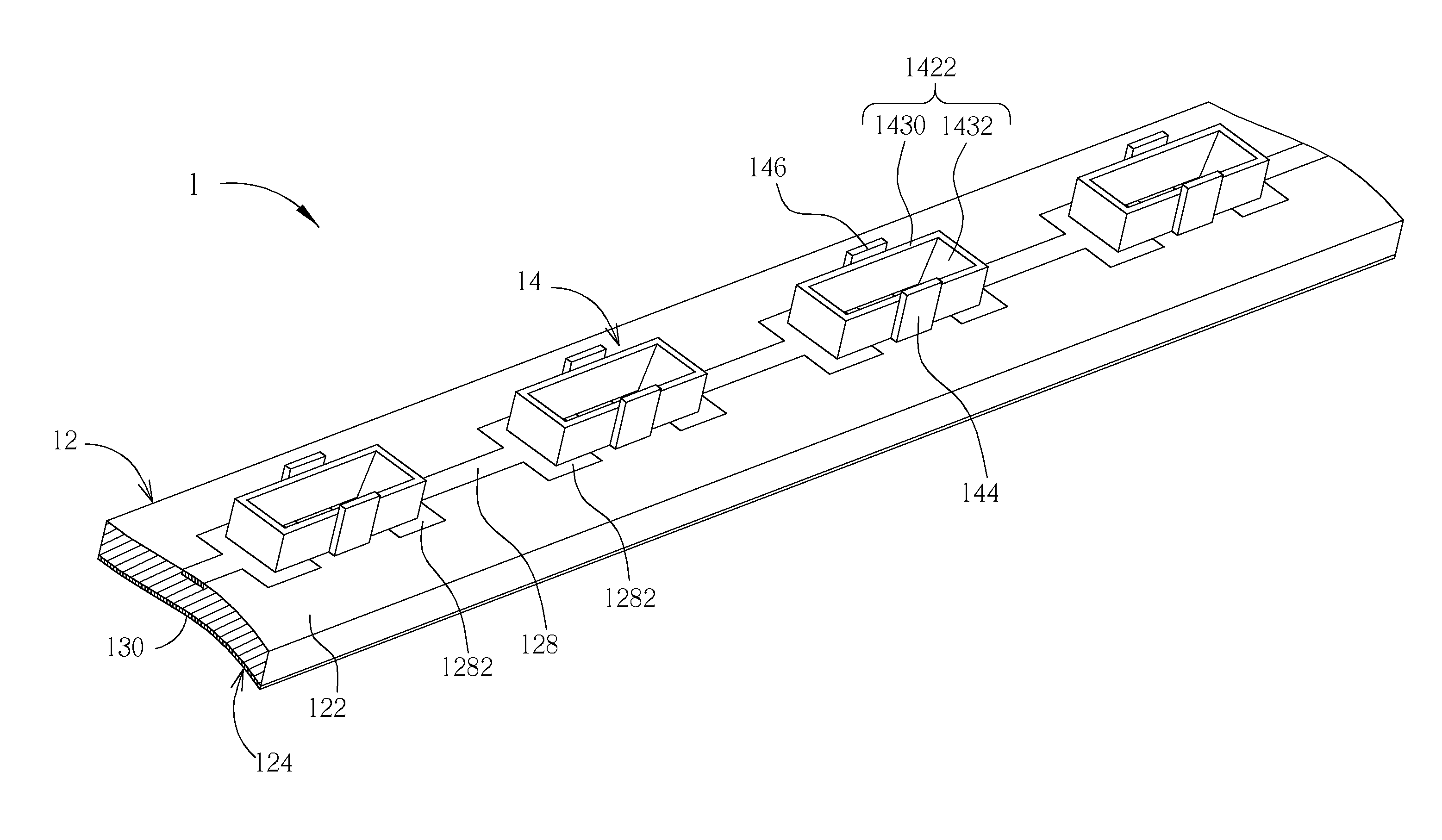
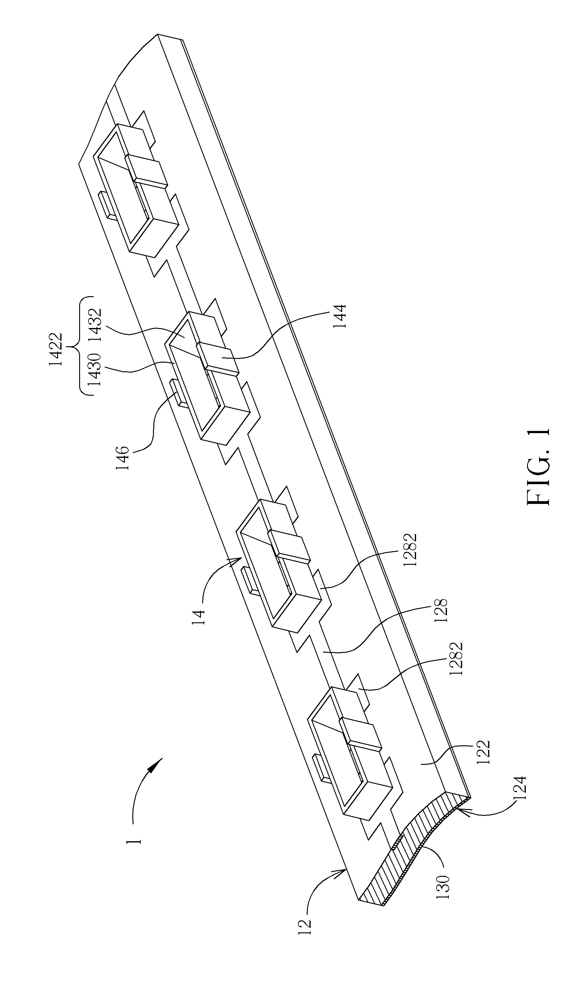
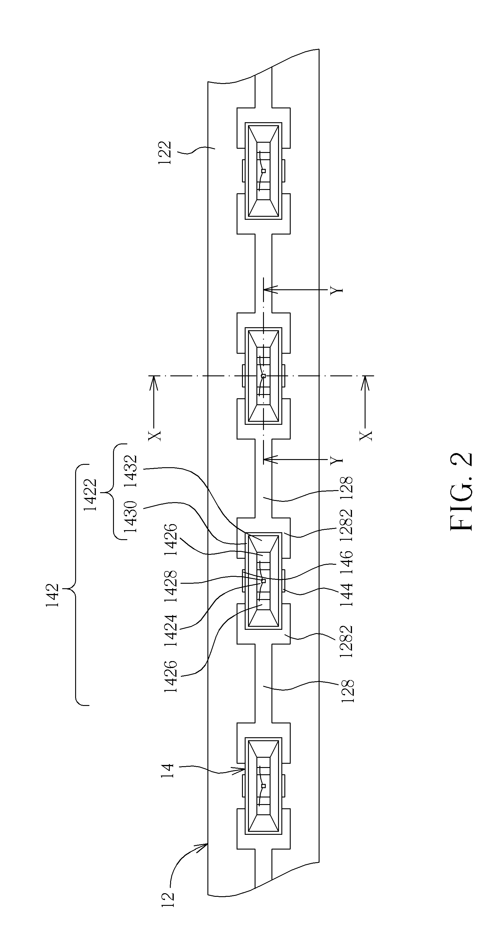
[0025]Please refer to FIGS. 1 through 4. FIG. 1 is a schematic diagram of a light source module 1 of a preferred embodiment according to the invention. FIG. 2 is a top view of the light source module 1 in FIG. 1. FIG. 3 is a sectional diagram along the line X-X of the light source module 1 in FIG. 1. FIG. 4 is another sectional diagram along the line Y-Y of the light source module 1 in FIG. 1. The light source module 1 includes a circuit board 12 and a plurality of light-emitting diodes 14 disposed on the circuit board 12. Each of the light-emitting diodes 14 includes a package unit 142, a first conductive support 144, and a second conductive support 146. The package unit 142 includes an insulation housing 1422, a heat-dissipating support 1424 and two electrode supports 1426 embedded in the insulation housing 1422, and a light-emitting diode chip 1428. Therein, the insulation housing 1422 includes a plastic member 1430 and a seal gel 1432. The plastic member 1430 is formed by inject...


PUM


Abstract

A light source module and a backlight module therewith are disclosed. The light source includes a circuit board and a light-emitting diode disposed on the circuit board. The light-emitting diode includes a package unit and a conductive support. The package unit includes an insulation housing, a heat-dissipating support embedded in the insulation housing, and a light-emitting diode chip disposed on the heat-dissipating support and encapsulated by the insulation housing. The light-emitting diode chip includes two electrodes, which are isolated form the heat-dissipating support. The insulation housing thereon defines a light-out surface. The conductive support is disposed on an exterior side surface of the insulation housing and connected to the heat-dissipating support to protrude out the light-out surface. Thereby, the protruding conductive support is also isolated from the two electrodes so as to perform ESD protection for avoiding unexpected damage to the light-emitting diode and extending service life thereof.

Description

BACKGROUND OF THE INVENTION[0001]1. Field of the Invention[0002]The invention relates to a light source module and a backlight module having the light source module, and especially relates to a light source module and a backlight module with anti-electrostatic discharge structure.[0003]2. Description of the Prior Art[0004]Light emitting diodes (LEDs) have advantages of small volume, long service life, and so on, so LEDs have been widely applied to various electronic apparatus with demand for light, such as illumination lamps, home appliances with optical indication function, computers, and communication products. Furthermore, as the light-emitting technology for LED develops, the luminous power and the stability of emitting light improve greatly. LEDs have been the mainstream of future light sources.[0005]There are many liquid crystal displays (LCDs) in the market using LEDs as light sources thereof. However, LEDs like other common semiconductor electronic components is easily affec...

Claims


Application Information

Patent Timeline
Patent Type & Authority Patents(United States)
IPC IPC(8): H01J1/02H01J61/52H01K1/58H01J7/24
CPCG02B6/0085H01L33/642G02B6/0031G02B6/0083G02F2202/22H01L2224/48091H01L2924/00014
Inventor YANG, CHAN-SHUNGLIN, SU-YICHEN, CHENG-CHUAN
Owner AU OPTRONICS CORP
Why Eureka
Try Eureka