Method and apparatus for measuring fiber twist by polarization tracking

a technology of optical fiber and polarization tracking, applied in the direction of optical apparatus testing, instruments, optical elements, etc., can solve the problem that traditional shape estimation fails to address torsion

Active Publication Date: 2012-11-08
THE UNITED STATES OF AMERICA AS REPRESENTED BY THE SECRETARY OF THE NAVY
View PDF3 Cites 22 Cited by
  • Summary
  • Abstract
  • Description
  • Claims
  • Application Information

AI Technical Summary

Problems solved by technology

Traditional shape estimation failed to address torsion.

Method used


Image

  • Method and apparatus for measuring fiber twist by polarization tracking
  • Method and apparatus for measuring fiber twist by polarization tracking
  • Method and apparatus for measuring fiber twist by polarization tracking

Examples


Embodiment Construction

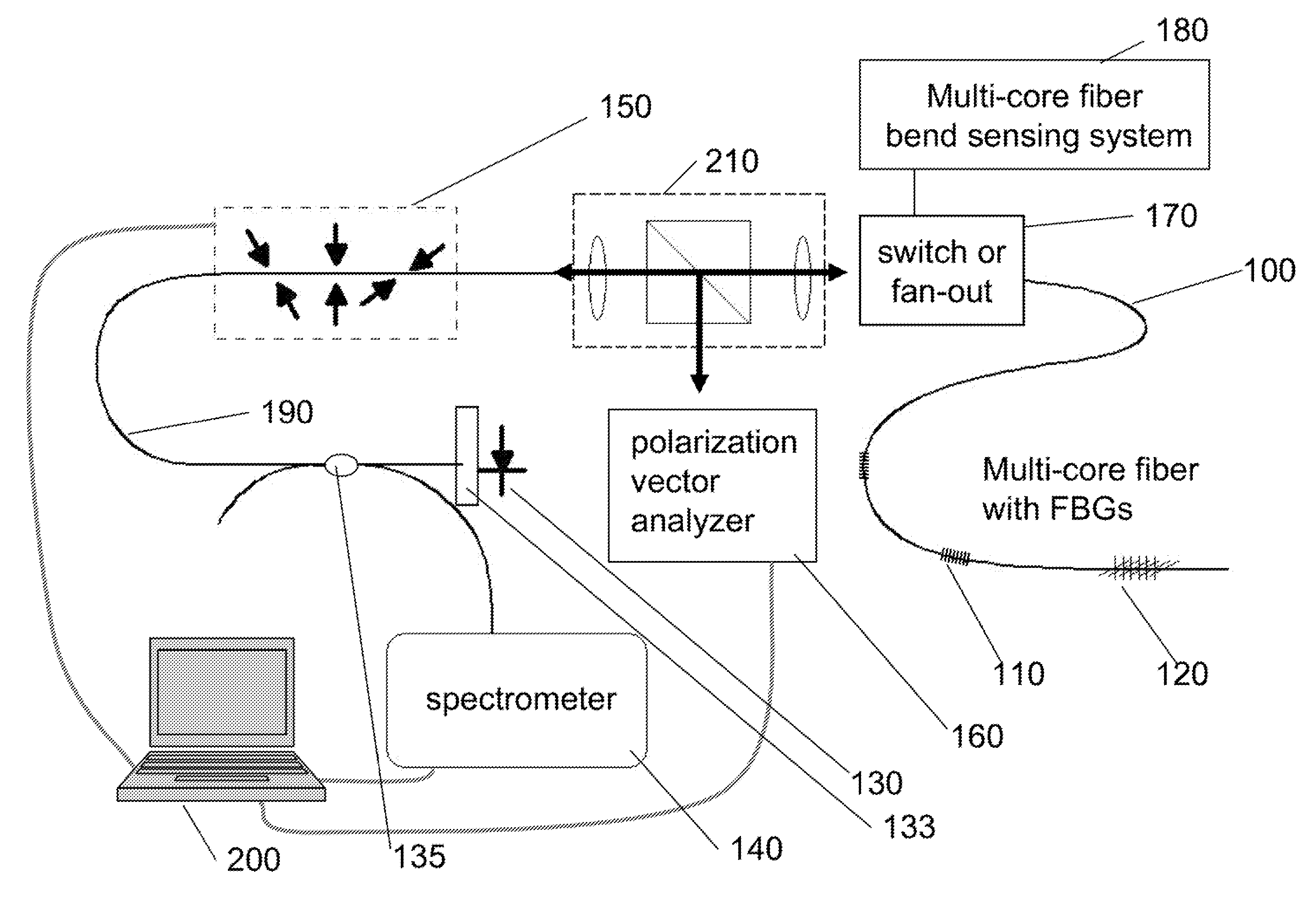
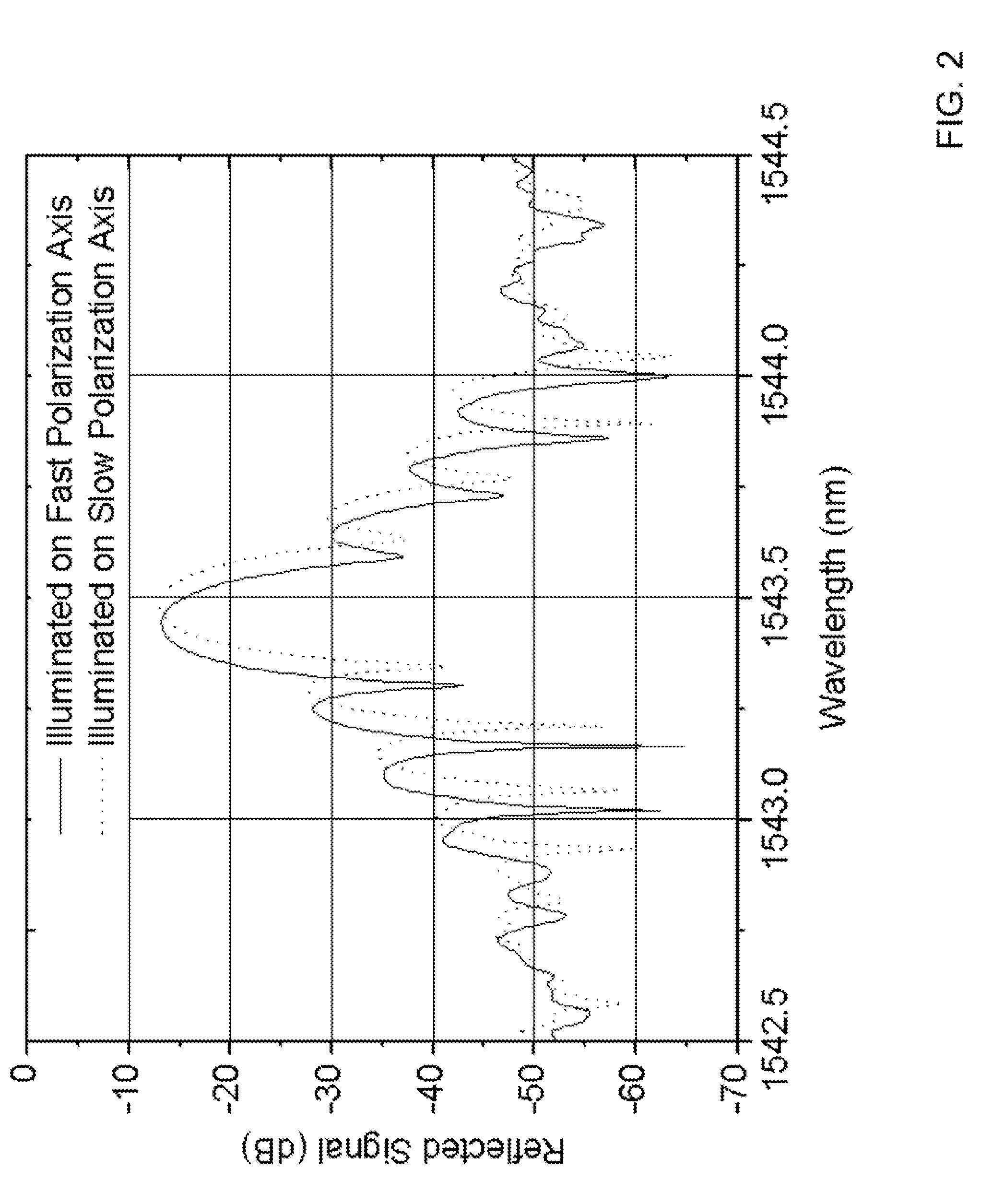
[0016]The basis for sensing twist in a fiber with the inventive apparatus and method may be conveyed by a thought experiment. Consider any of several optical elements which exhibit reflectivity which is dependent upon the polarization of the light illuminating their surfaces. Determination of the optic's rotational orientation (with 180-degree degeneracy) is readily obtained by measuring the reflected intensity of a linearly polarized, probing light beam as the light's polarization axis is systematically swept through 360 degrees. Determining the orientation of a FBG with PDR is an extension of this principle. In this case, the probing light travels along an optical path which modifies the SOP of propagating light in the presence of bending and twisting according to well understood physical laws. Further, a fiber Bragg grating may exhibit a sharp dependence of reflectivity on wavelength.

[0017]An embodiment of the invention includes a method comprising the following steps or operatio...


PUM

PropertyMeasurementUnit
Bragg wavelengthaaaaaaaaaa
wavelengthsaaaaaaaaaa

Abstract

A method of measuring fiber twist in a multi-core optical fiber bearing an FBG with polarization dependent reflectivity. The state of polarization of the launched light is adjusted until the reflected FBG wavelength is maximal, indicating that light reaching the FBG is linearly polarized, and the polarization axis of the light reaching the FBG is aligned with the slow birefringent axis of the FBG; the SOP of launched light is now measured. Bending experienced by the fiber is measured conventionally, and birefringence produced by bending of the multi-core optical fiber is calculated. A candidate amount of twist between the launch location and the FBG is proposed, and the corresponding twist-induced birefringence is calculated. When calculations show that light with the launched SOP becomes linearly polarized and aligned with the FBG after traversing a fiber section with the calculated birefringences and proposed rotation, the amount of twist has been properly identified.

Description

CROSS-REFERENCE TO RELATED APPLICATION[0001]This application claims priority to U.S. Provisional Patent. Application Ser. No. 61 / 112,227, entitled “MEASUREMENT OF FIBER TWIST BY POLARIZATION TRACKING,” to Askins. This application is a divisional of U.S. patent application Ser. No. 12 / 614,309 to Askins.FIELD OF THE INVENTION[0002]The present invention relates in general to a method and apparatus for measuring twist in an optical fiber which may concurrently experience bending, and more particularly to a method and apparatus for measuring twist by tracking polarization of light in the optical fiber.BACKGROUND OF THE INVENTION[0003]For a range, of applications, it is useful to deduce the shape that a flexible optical fiber occupies in space using only measurements of light traveling within the fiber; this shape generally includes both bending and twisting deflections. Traditional shape estimation failed to address torsion. Such a failure is permissible in a torsionally rigid optical fi...

Claims


Application Information

Patent Timeline
Patent Type & Authority Applications(United States)
IPC IPC(8): G01N21/23
CPCG01M11/088G01M11/3181G02B6/274G01D5/35354G01D5/344G01D5/35316G02B6/29319
Inventor ASKINS, CHARLES G.
Owner THE UNITED STATES OF AMERICA AS REPRESENTED BY THE SECRETARY OF THE NAVY
Why Eureka
Try Eureka