
Incorporating video meta-data in 3D models

a technology of video metadata and 3d models, applied in the field of creating an augmented virtual environment, can solve the problems of difficult object recognition and tracking by the human eye, and difficult understanding and determining

Active Publication Date: 2012-11-08
KYNDRYL INC
View PDF1 Cites 99 Cited by
  • Summary
  • Abstract
  • Description
  • Claims
  • Application Information

AI Technical Summary

Benefits of technology

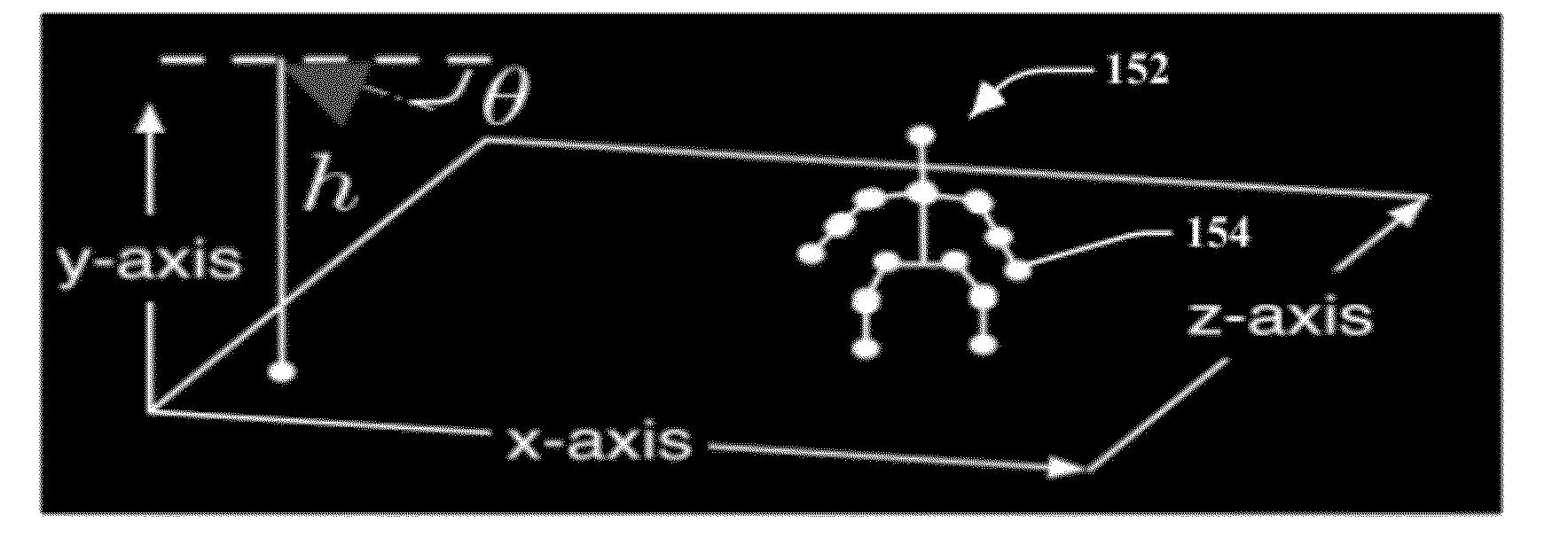
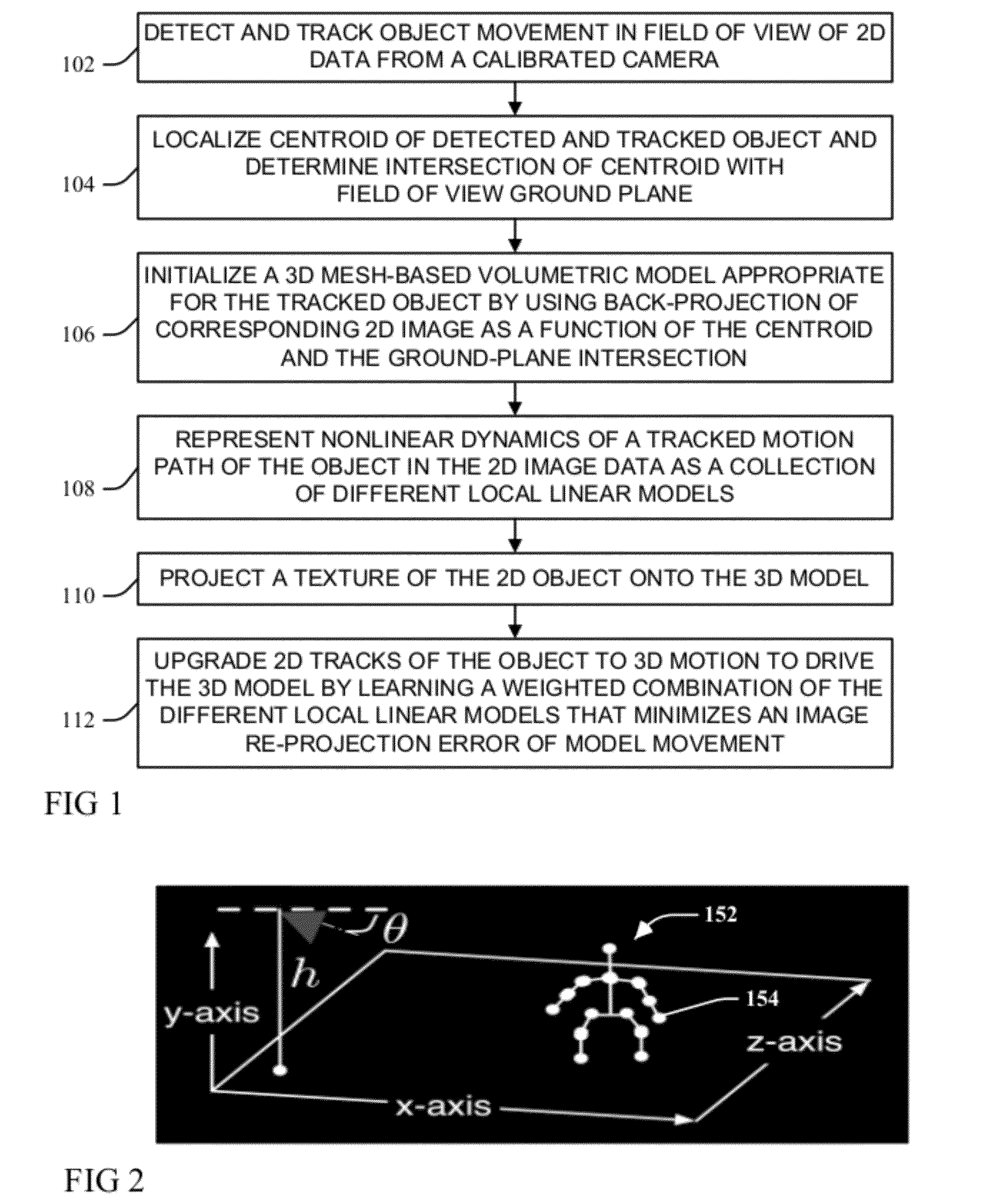
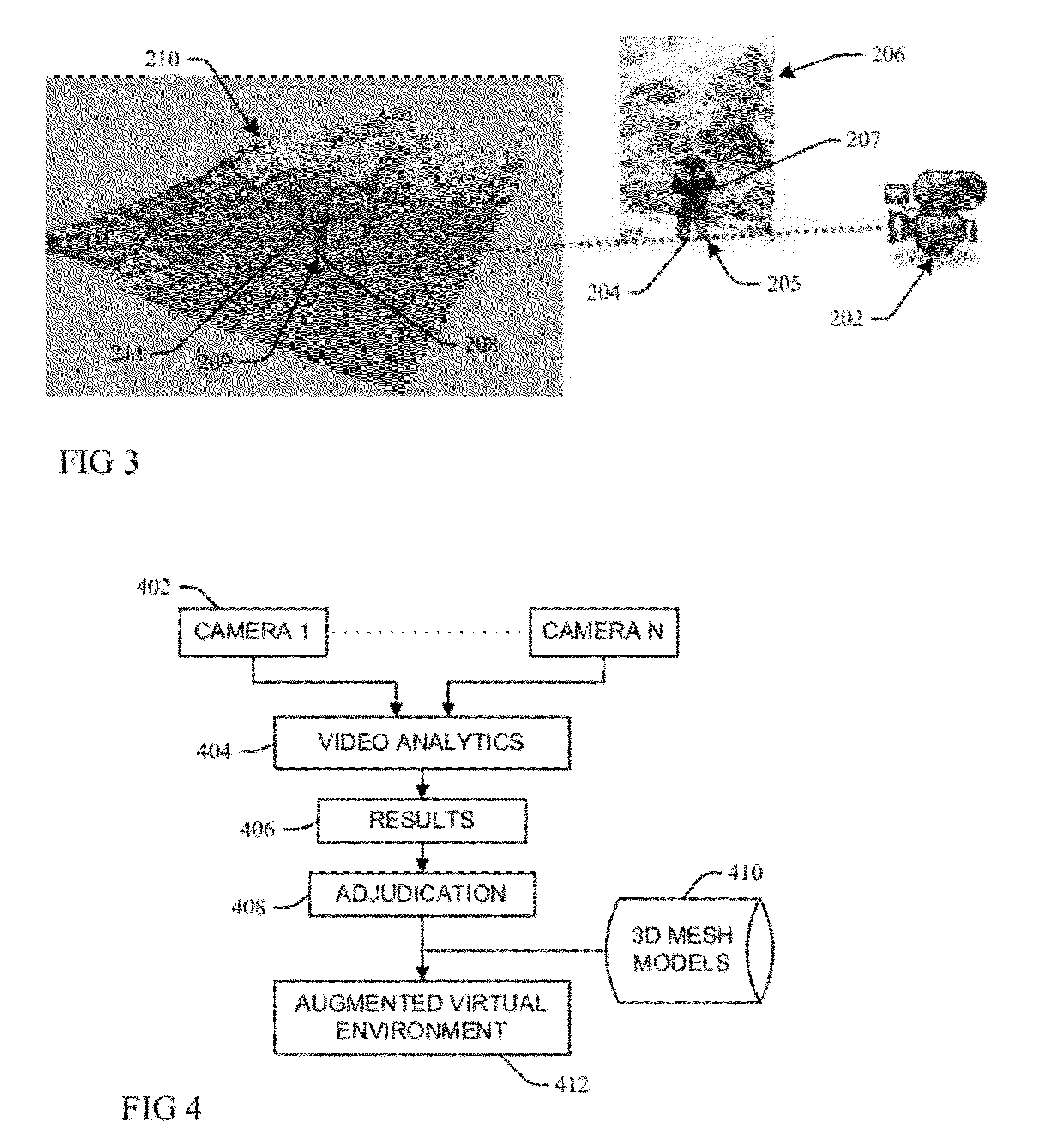
The present invention provides a method for representing objects tracked within 2D video data by 3D models. The method involves localizing the centroid of a moving object detected and tracked within a field of view environment of a calibrated video camera, and determining the intersection of the centroid with a ground-plane within the field of view environment. A 3D mesh-based volumetric model is initialized based on the centroid and ground-plane intersection, and nonlinear dynamics of the object's motion path is represented as a collection of different local linear models. The texture of the object is projected onto the 3D model, and the 2D tracks of the object are upgraded to 3D motion to drive the 3D model in dynamic mesh-based 3D. The invention also provides a system for providing a service for representing objects tracked within 2D video data by 3D models.

Problems solved by technology

Understanding and determining the import of the various object movements, for example a person approaching an area or taking some sort of action that exposes that person or others to a heightened hazard risk, may be difficult from 2D video data streams.
Human operators may be required to simultaneously review and analyze multiple monitors or display windows for object movements, and the 2D nature of video data may make object recognition and tracking by the human eye difficult, particularly in visually rich or noisy environments.
However, to adequately render 3D models such systems require other data inputs, for example data from other cameras or other devices, such as range, image and / or object tracking sensors.

Method used


Image

  • Incorporating video meta-data in 3D models
  • Incorporating video meta-data in 3D models
  • Incorporating video meta-data in 3D models

Examples


Embodiment Construction

[0017]As will be appreciated by one skilled in the art, aspects of the present invention may be embodied as a system, method or computer program product. Accordingly, aspects of the present invention may take the form of an entirely hardware embodiment, an entirely software embodiment (including firmware, resident software, micro-code, etc.) or an embodiment combining software and hardware aspects that may all generally be referred to herein as a “circuit,”“module” or “system.” Furthermore, aspects of the present invention may take the form of a computer program product embodied in one or more computer readable medium(s) having computer readable program code embodied thereon.

[0018]Any combination of one or more computer readable medium(s) may be utilized. The computer readable medium may be a computer readable signal medium or a computer readable storage medium. A computer readable storage medium may be, for example, but not limited to, an electronic, magnetic, optical, electromagne...


PUM


Abstract

A moving object detected and tracked within a field of view environment of a 2D data feed of a calibrated video camera is represented by a 3D model through localizing a centroid of the object and determining an intersection with a ground-plane within the field of view environment. An appropriate 3D mesh-based volumetric model for the object is initialized by using a back-projection of a corresponding 2D image as a function of the centroid and the determined ground-plane intersection. Nonlinear dynamics of a tracked motion path of the object are represented as a collection of different local linear models. A texture of the object is projected onto the 3D model, and 2D tracks of the object are upgraded to 3D motion to drive the 3D model by learning a weighted combination of the different local linear models that minimizes an image re-projection error of model movement.

Description

BACKGROUND[0001]The present invention relates to creating an Augmented Virtual Environment (AVE) that augments two-dimensional (2D) video data with three-dimensional (3D) understandings of objects contained within the video data environment.[0002]Understanding and determining the import of the various object movements, for example a person approaching an area or taking some sort of action that exposes that person or others to a heightened hazard risk, may be difficult from 2D video data streams. Human operators may be required to simultaneously review and analyze multiple monitors or display windows for object movements, and the 2D nature of video data may make object recognition and tracking by the human eye difficult, particularly in visually rich or noisy environments.[0003]Object tracking and recognition may be improved if 2D video data is provided in an Augmented Virtual Environment (AVE) that creates 3D scene models of objects present in the video data, as recognizing and trac...

Claims


Application Information

Patent Timeline
Patent Type & Authority Applications(United States)
IPC IPC(8): G06K9/00
CPCG06T19/006G06T13/20G06T7/20G06T7/2046G06K9/00208G06T17/00G06T7/251H04N23/60G06V20/647
Inventor BROWN, LISA M.DATTA, ANKURFERIS, ROGERIO S.PANKANTI, SHARATHCHANDRA U.
Owner KYNDRYL INC
Learn More