Electrosurgical instrument

Active Publication Date: 2012-11-08
OLYMPUS WINTER & IBE
View PDF1 Cites 28 Cited by
  • Summary
  • Abstract
  • Description
  • Claims
  • Application Information

AI Technical Summary

Benefits of technology

[0028]characterised in that the device also includes a guide member located within the sheath and forming compartments for each of the electrically conductive wires, the guide member being rotatable within the sheath to prevent the electric

Problems solved by technology

Each of the above designs, however, suffers from difficulties in completing the cutting of tissue as the wires are drawn against the end of the sheath.
However, when the wires are withdrawn within the sheath there is a risk of the wires becoming twisted resulting in shorting between the wires.
Thi

Method used


Image

  • Electrosurgical instrument
  • Electrosurgical instrument
  • Electrosurgical instrument

Examples


Embodiment Construction

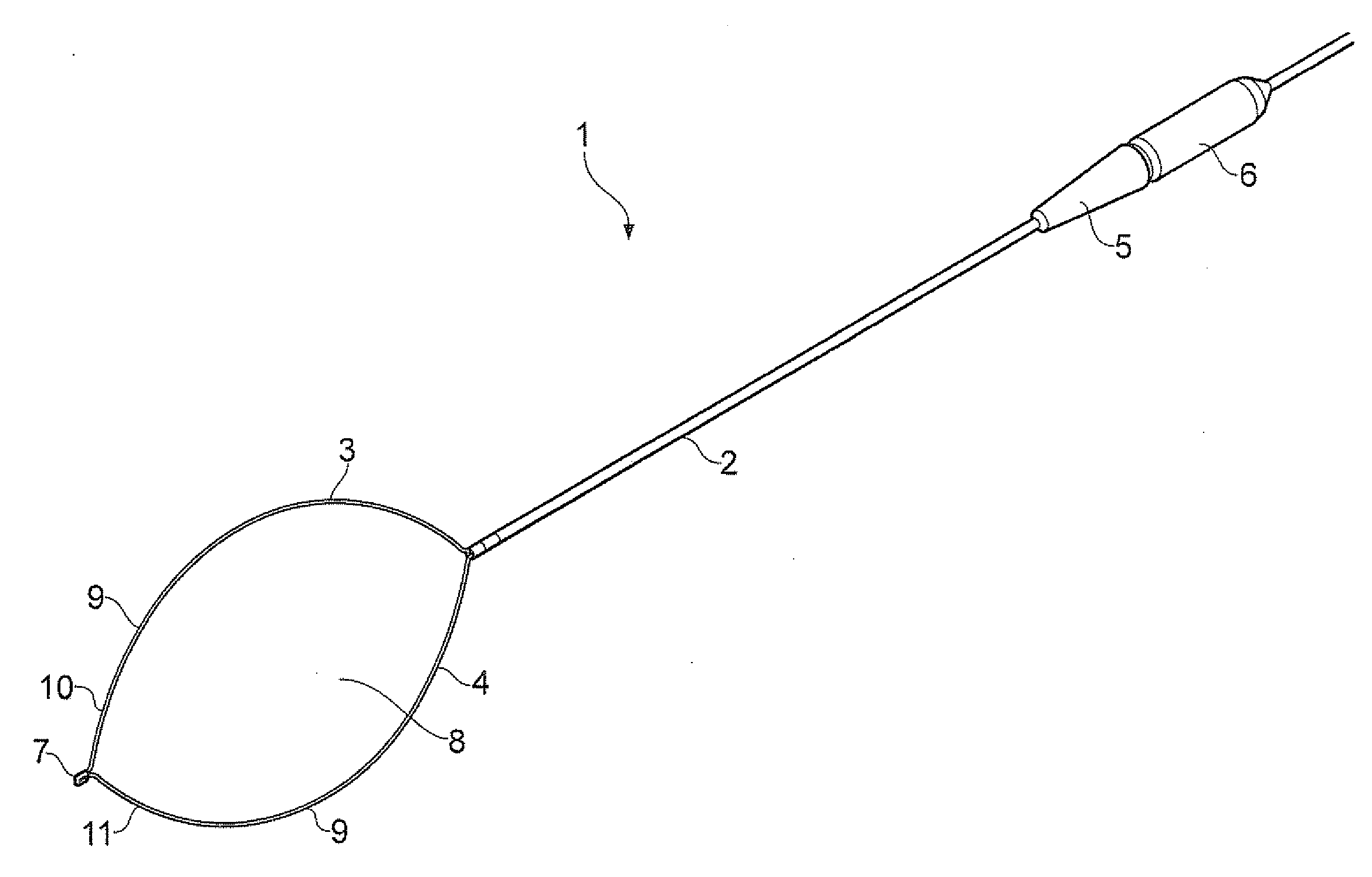
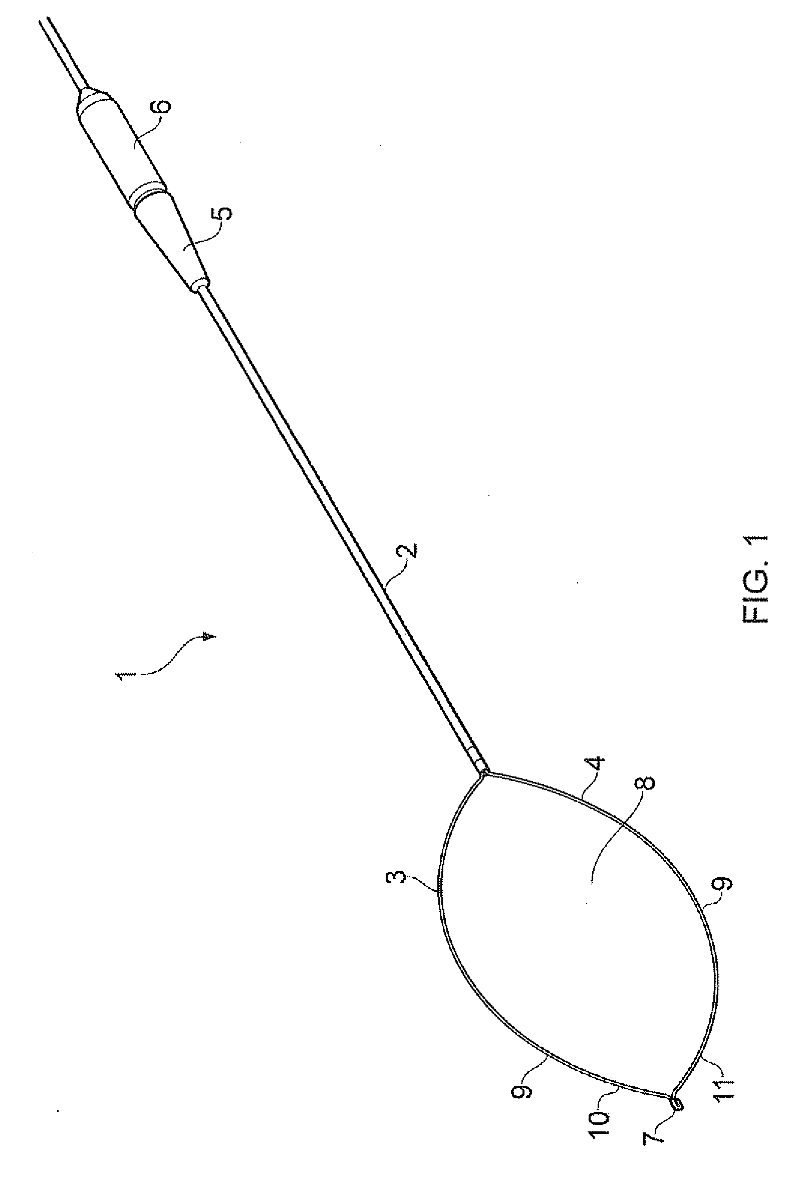
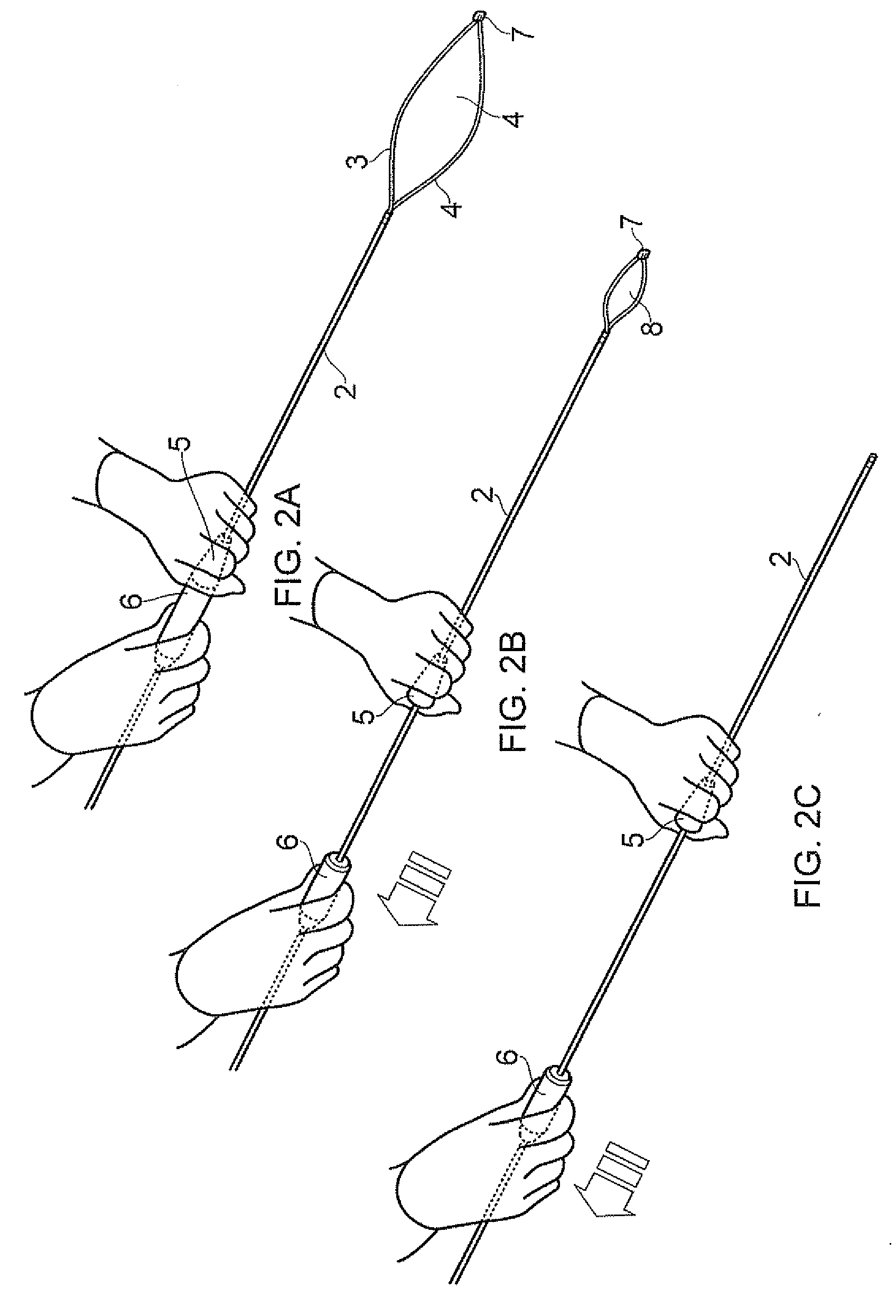
[0041]Referring to FIGS. 1 & 2, a bipolar snare is shown generally at 1, and comprises an elongated tubular sheath 2 containing first and second wires 3 and 4. A first handle 5 is provided for manoeuvring the sheath 2, and a second handle 6 is attached to the wires 3&4, such that longitudinal movement of the second handle 6 with respect the first handle 5 causes the wires 3&4 to be moved longitudinally with respect to the sheath 2, as shown in FIGS. 2A, 2B &2C.

[0042]An insulating connector 7 of a ceramic material joins the distal end of the first and second wires 3&4 one to the other, so as to form a loop shown generally at 8. The wires 3&4 are covered with an insulating covering 9 along the majority of their length, but are left exposed as shown at 10 and 11 towards their distal end.

[0043]When fully extended, the wires form a hexagonal shape as shown in FIGS. 1 & 3. This allows the loop 8 to be placed over a piece of tissue to be resected, such as a polyp or other small tissue mass...


PUM


Abstract

A bipolar snare including an elongated tubular electrically insulating sheath, a pair of elongated flexible electrically conductive wires disposed within the sheath, and an electrically insulating connector disposed at the distal ends of the wires mechanically connecting the distal ends of the wires to form a loop projecting from the distal end of the sheath. The wires are provided with electrical insulation covering all but a selected portion of each of the wires. The device also includes a guide member located within the sheath and forming compartments for each of the electrically conductive wires, the guide member being rotatable within the sheath. The guide member is also set back from the distal end of the sheath to an extent such that the whole of the loop including at least part of the connector is capable of being received within the sheath.

Description

TECHNICAL FIELD[0001]This invention relates to an electrosurgical instrument and in particular to a bipolar snare device.BACKGROUND TO THE INVENTION[0002]Bipolar snares are known, and examples are given in U.S. Pat. Nos. 4,493,320, 4,905,691 and 5,078,716. Each of these designs have a pair of wires extending from an elongate sheath, the wires being separated by an insulating divider to form first and second bipolar electrodes. An electrosurgical current flows between the wires, cutting the tissue as the wires are drawn into the sheath.[0003]Each of the above designs, however, suffers from difficulties in completing the cutting of tissue as the wires are drawn against the end of the sheath.[0004]U.S. Pat. No. 5,078,716 describes a bipolar snare in which the loop and connector are be received within the sheath. However, when the wires are withdrawn within the sheath there is a risk of the wires becoming twisted resulting in shorting between the wires. This is countered by an additiona...

Claims


Application Information

Patent Timeline
IPC IPC(8): A61B18/14
CPCA61B2018/141A61B18/14
Inventor JENKINS, ANDREW EDWARDBRIGGS, KERRY SIMPSONWARREN, PHILIP JOHN
Owner OLYMPUS WINTER & IBE
Why Eureka
Try Eureka