Electrosurgical instrument

a surgical instrument and electrode technology, applied in the field of electrosurgical instruments, can solve the problems of shortening the wires, unable to complete the surgical procedure, and difficulty in tissue cutting,

Active Publication Date: 2016-01-12
OLYMPUS WINTER & IBE
View PDF20 Cites 1 Cited by
  • Summary
  • Abstract
  • Description
  • Claims
  • Application Information

AI Technical Summary

Benefits of technology

[0015]One advantageous feature of embodiments of the present invention is that the guide member prevents the electrically conductive wires from becoming twisted, but still allows the loop including at least part of the insulating connector to be received within the sheath.
[0016]In addition, the guide member of embodiments of the present invention also prevents shorting between the wires, and yet still allows for efficient tissue cutting, even when the wires are very close to the end of the sheath.
[0018]In some embodiments of the present invention, the guide member conveniently comprises a cylindrical member with an I-shaped cross section forming two compartments, one for each of the electrically conductive wires. In this way, the wires are each contained separately within their own compartment, preventing the two wires from coming into contact with each other. If the wires are rotated, the guide member rotates within the sheath to maintain the separation of the wires one from the other.
[0020]In a particularly advantageous construction, the guide member is provided with an extension at its distal end, the extension being capable of separating the electrically conductive wires as they exit the guide member. The extension is conveniently in the form of a planar partition, and is preferably movable between two positions, a first extended position, and a second retracted position to provide space for the electrically insulating connector to at least partly enter the sheath. The extension is conveniently formed of a flexible material, capable of collapsing into its second position. In this way, the extension separates the conductive wires, while collapsing to allow the whole of the loop, including some or all of the insulating connector, to enter the sheath. Whether in its first or second position, the extension separates the two wires, and yet is still rotatable within the sheath.
[0030]As before, the guide member conveniently comprises a cylindrical member with an I-shaped cross section forming two compartments, one for each of the electrically conductive wires, or alternatively a cylindrical member with two lumens therein, one for each of the electrically conducting wires. Similarly, the extension is conveniently in the form of a planar partition, and movable between two positions, a first extended position in which it separates the electrically conductive wires, and a second retracted position to provide space for the electrically insulating connector to at least partly enter the sheath. As before, the extension is preferably formed of a flexible material, capable of collapsing into its second position. The extension on the guide member maintains the separation of the two wires, while the ability to move between two positions allows for the whole of the loop, including some or all of the insulating connector, to be withdrawn into the sheath, maintaining the cutting efficiency of the device throughout the whole of the cutting process.

Problems solved by technology

Each of the above designs, however, suffers from difficulties in completing the cutting of tissue as the wires are drawn against the end of the sheath.
However, when the wires are withdrawn within the sheath there is a risk of the wires becoming twisted resulting in shorting between the wires.
This additional insulation prevents shorting between the wires, but results in the less efficient cutting of tissue, especially when the wires are very close to the sheath.
Thus the cutting effectiveness of the snare device, particularly when the wires are close to the end of the sheath, is reduced.

Method used


Image

  • Electrosurgical instrument
  • Electrosurgical instrument
  • Electrosurgical instrument

Examples


Embodiment Construction

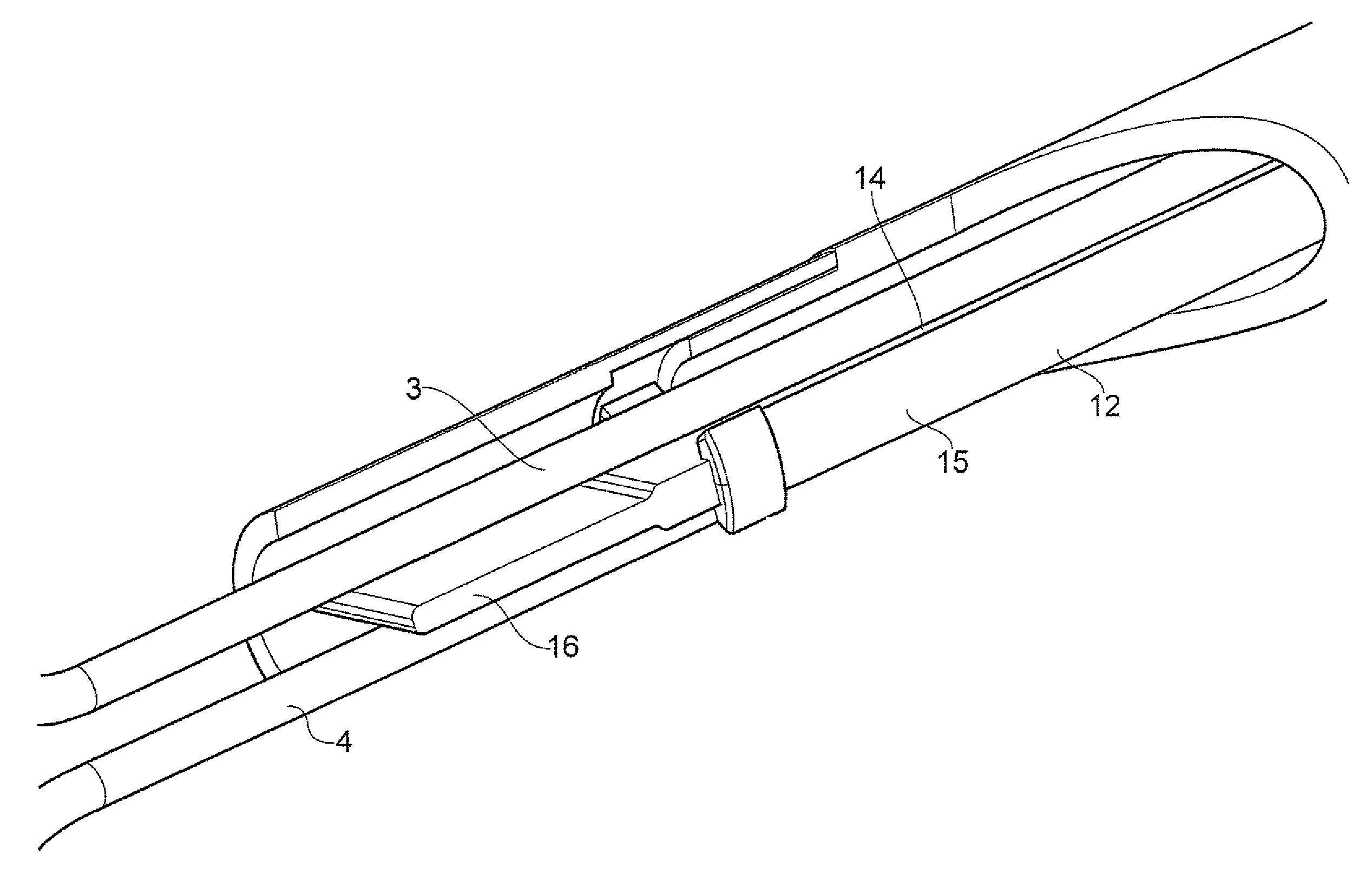
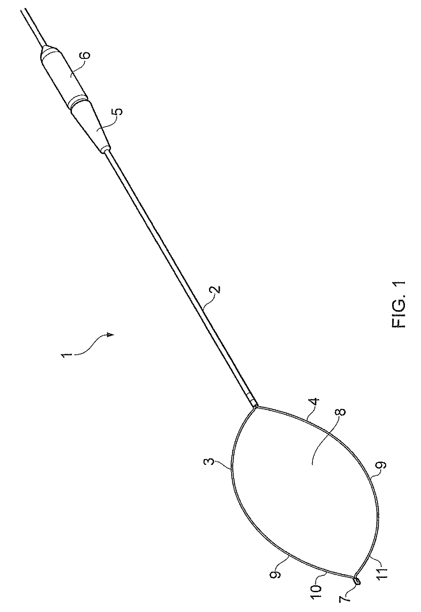
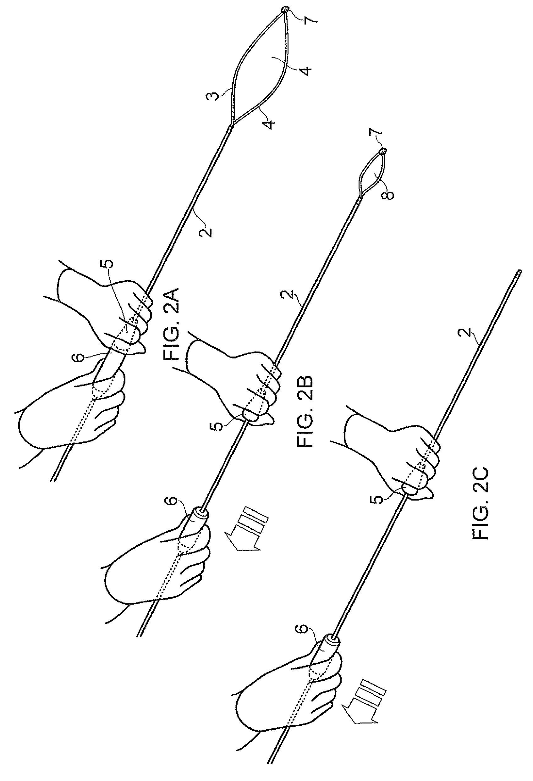
[0042]Referring to FIGS. 1 & 2, a bipolar snare is shown generally at 1, and comprises an elongated tubular sheath 2 containing first and second wires 3 and 4. A first handle 5 is provided for maneuvering the sheath 2, and a second handle 6 is attached to the wires 3&4, such that longitudinal movement of the second handle 6 with respect the first handle 5 causes the wires 3&4 to be moved longitudinally with respect to the sheath 2, as shown in FIGS. 2A, 2B &2C.

[0043]An insulating connector 7 of a ceramic material joins the distal end of the first and second wires 3&4 one to the other, so as to form a loop shown generally at 8. The wires 3&4 are covered with an insulating covering 9 along the majority of their length, but are left exposed as shown at 10 and 11 towards their distal end.

[0044]When fully extended, the wires form a hexagonal shape as shown in FIGS. 1 & 3. This allows the loop 8 to be placed over a piece of tissue to be resected, such as a polyp or other small tissue mass...


PUM


Abstract

A bipolar snare including an elongated tubular electrically insulating sheath, a pair of elongated flexible electrically conductive wires disposed within the sheath, and an electrically insulating connector disposed at the distal ends of the wires mechanically connecting the distal ends of the wires to form a loop projecting from the distal end of the sheath. The wires are provided with electrical insulation covering all but a selected portion of each of the wires. The device also includes a guide member located within the sheath and forming compartments for each of the electrically conductive wires, the guide member being rotatable within the sheath. The guide member is also set back from the distal end of the sheath to an extent such that the whole of the loop including at least part of the connector is capable of being received within the sheath.

Description

TECHNICAL FIELD[0001]This invention relates to an electrosurgical instrument and in particular to a bipolar snare device.BACKGROUND TO THE INVENTION[0002]Bipolar snares are known, and examples are given in U.S. Pat. Nos. 4,493,320, 4,905,691 and 5,078,716. Each of these designs have a pair of wires extending from an elongate sheath, the wires being separated by an insulating divider to form first and second bipolar electrodes. An electrosurgical current flows between the wires, cutting the tissue as the wires are drawn into the sheath.[0003]Each of the above designs, however, suffers from difficulties in completing the cutting of tissue as the wires are drawn against the end of the sheath.[0004]U.S. Pat. No. 5,078,716 describes a bipolar snare in which the loop and connector are be received within the sheath. However, when the wires are withdrawn within the sheath there is a risk of the wires becoming twisted resulting in shorting between the wires. This is countered by an additiona...

Claims


Application Information

Patent Timeline
Patent Type & Authority Patents(United States)
IPC IPC(8): A61B18/14
CPCA61B18/14A61B2018/141
Inventor JENKINS, ANDREW EDWARDBRIGGS, KERRY SIMPSONWARREN, PHILIP JOHN
Owner OLYMPUS WINTER & IBE
Why Eureka
Try Eureka