Method For Using Dynamic Target Region For Well Path/Drill Center Optimization

a dynamic target region and optimization method technology, applied in the field of hydrocarbon production, can solve problems such as limiting the selection of optimal drill center configuration

Active Publication Date: 2012-11-15
EXXONMOBIL UPSTREAM RES CO
View PDF8 Cites 86 Cited by
  • Summary
  • Abstract
  • Description
  • Claims
  • Application Information

AI Technical Summary

Problems solved by technology

1. Geoscientist selects potential targets based on geologic interpretation and understanding of reservoir properties.
2. Multiple well trajectories are designed and given to the drilling engineer for more detailed well design and analysis.
3. The drill center locations are selected or modified based on the results of the well design and analysis step.
4. Changes to the target location(s), number of targets, or basic trajectory parameters are made during the iterative steps by geologists and drilling engineers; depending on the complexity of the well path and geology, the final drill center locations and well trajectory may take many such iterations and several weeks / months of calendar time.
Significant challenges remain such as integrating optimal well path constraints with finding optimal drill center locations, since the conflicting objectives of well targets, well paths and / or drill center locations may complicate the optimization process which would lead to sub-optimal solutions.
Furthermore, as stated by Prange et al., the proposed multi-well trajectories optimization that relies on a set of pre-selected fixed targets could further limit the selection of optimal drill center configuration since the constraints on the drillable well trajectories to multiple fixed targets would add extra complexity to the overall optimization processes and may not lead to an optimum solution.

Method used


Image

  • Method For Using Dynamic Target Region For Well Path/Drill Center Optimization
  • Method For Using Dynamic Target Region For Well Path/Drill Center Optimization
  • Method For Using Dynamic Target Region For Well Path/Drill Center Optimization

Examples


example 1

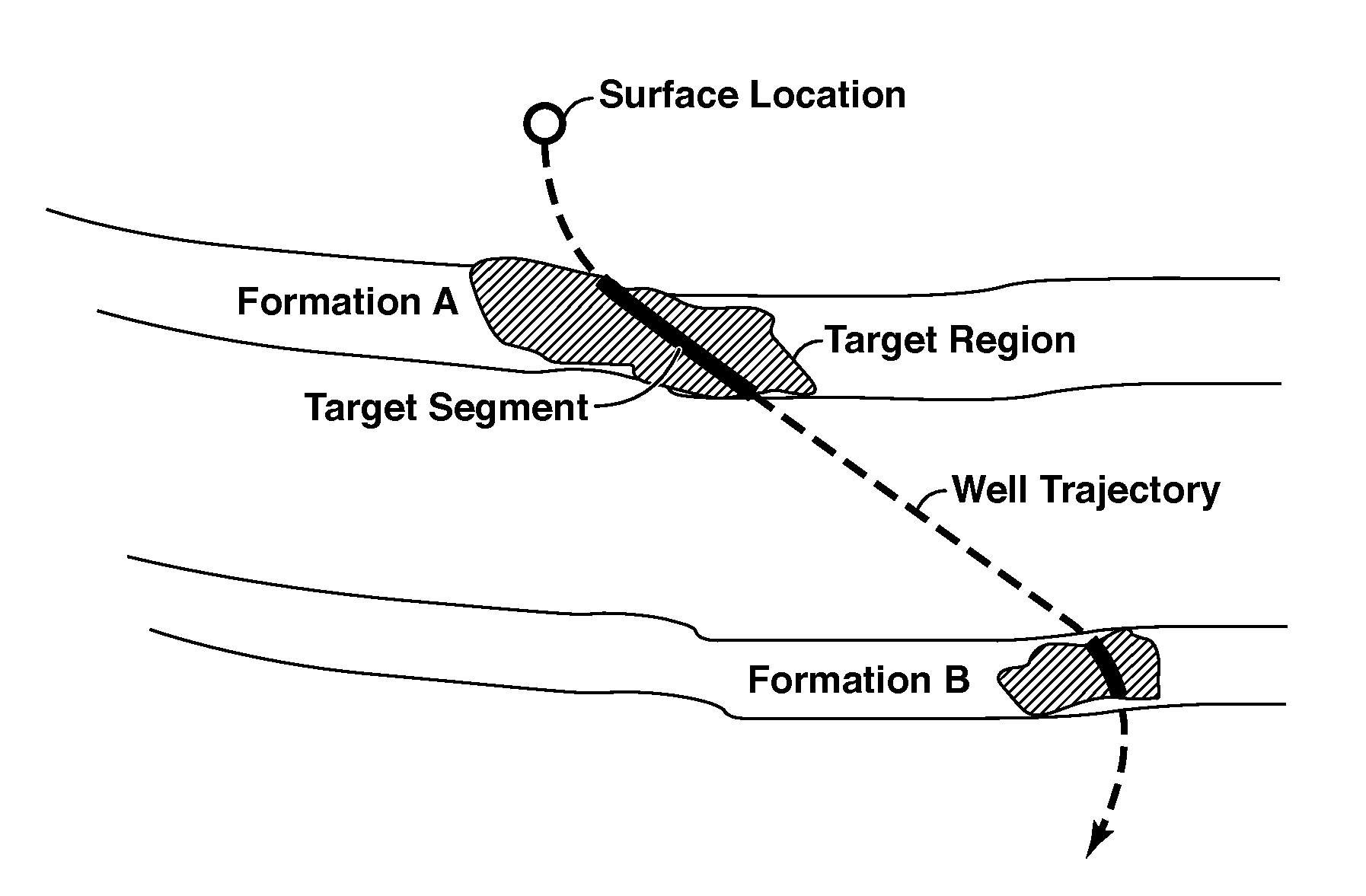
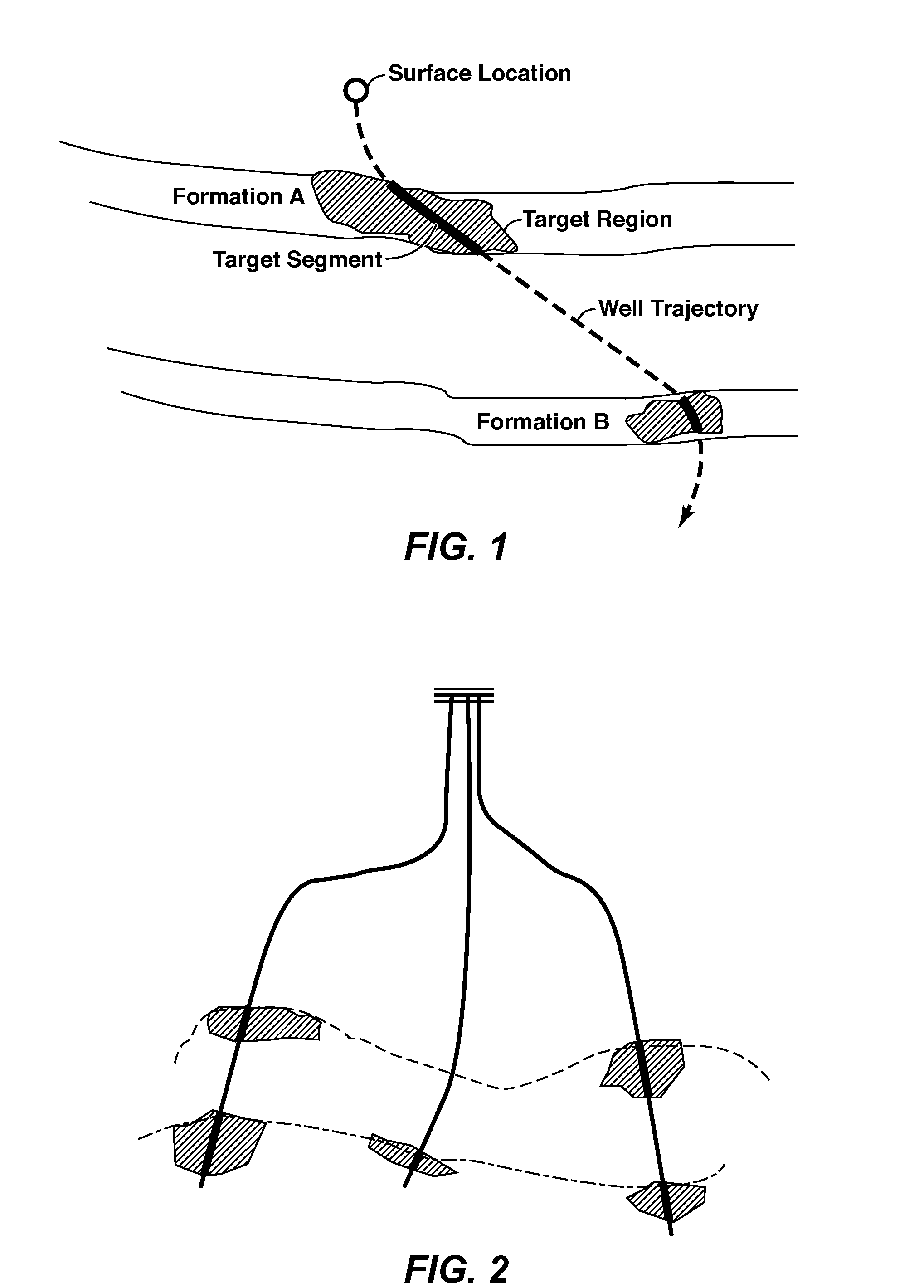
[0043]Drill center planning and well path optimization based on user defined polygonal area in the reservoir.

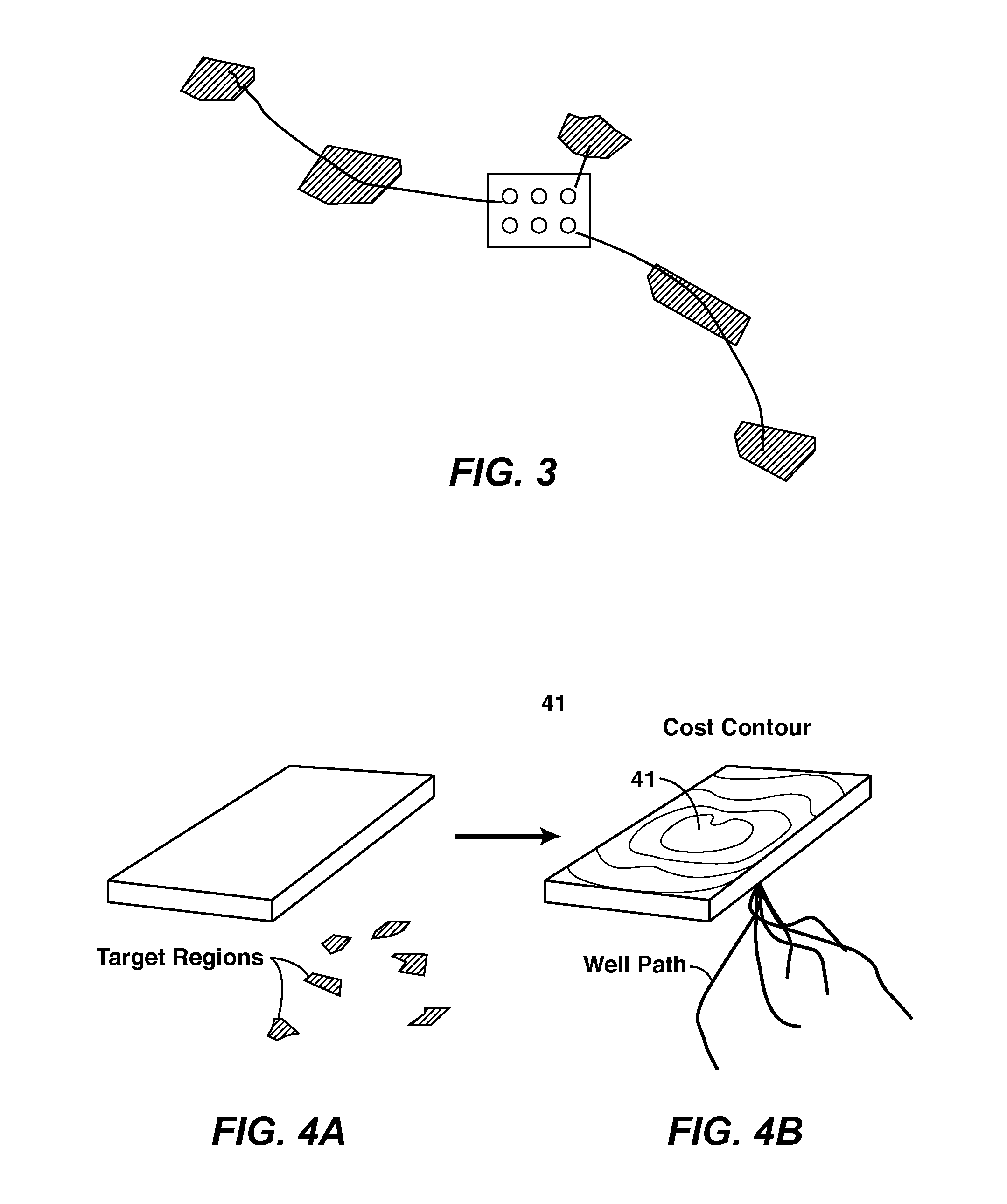
[0044]Data input: A set of six polygonal areas R(i), identified as Dynamic Target Regions from reservoir properties such as amplitude mapping on the top surface of the reservoirs. For each R(i), a well trajectory is expected to be derived based on user preference parameters such as build length and dog-leg angle criteria. This example needs only a simple cost function based on the total measured length of the entire well with fixed dollars per feet. The drill center is designed with 6 slots and each slot would host the start of a well trajectory to reach one of the proposed DTRs. The location of the drill center is constrained to a specified rectangular surface area (41 in FIG. 4A).

[0045]Objective function: Find an optimal drill center location with optimal defined by the following:

[0046]Minimize total cost of drilling well trajectories˜ΣMD(i) for i=1 to N,

[0047]where N=6 is ...

example 2

[0052]Drill center planning and well path optimization using engineering / reservoir properties as proxy.

[0053]Data input: A set of volumetric defined regions VR(i), identified as Dynamic Target Regions from the reservoir properties such as amplitude attributes on a 3D seismic data volume. For each VR(i), a well trajectory is derived based on the user preference parameters described in Example 1. Additionally, a set of geological constraints such as distance to fault surfaces, salt domes are imposed. The conditions of anti-collision to the geological objects can be determined by the geometric distance calculations and / or by calculated proxy volumes encompassing the 3D earth model where each voxel contains information on the relationship to the closest geological objects. To maximize the total “reward” of well trajectories with Target Segments penetrating the VR(i), the reward value can be determined by the total accumulated value within the defined region and / or by other performance m...


PUM


Abstract

Method for determining one or more optimal well trajectories and a drill center location for hydrocarbon production. A well path and drill center optimization problem (55) is solved in which one constraint is that a well trajectory must intersect a finite size target region (61) in each formation of interest, or in different parts of the same formation. The finite target size provides flexibility for the optimization problem to arrive at a more advantageous solution. Typical well path optimization constraints are also applied, such as anti-collision constraints and surface site constraints (62).

Description

CROSS-REFERENCE TO RELATED APPLICATION[0001]This application claims the benefit of U.S. Provisional Patent Application 61 / 301,045 filed 3 Feb. 2010 entitled METHOD FOR USING DYNAMIC TARGET REGION FOR WELL PATH / DRILL CENTER OPTIMIZATION, the entirety of which is incorporated by reference herein.FIELD OF THE INVENTION[0002]The invention relates generally to the field of hydrocarbon production, and more particularly to conducting drilling planning for determining the configuration of drill centers and / or sub-sea templates within a three dimensional earth model.BACKGROUND OF THE INVENTION[0003]While the task of drilling planning and well path / well trajectory identifications is primarily an engineering function, a critical objective of drilling planning is to maximize the output of the oil / gas extraction from given reservoirs. Understanding of the reservoir properties as well as geological constraints, such as potential hazard avoidance, is vital to the success of a drilling program.[000...

Claims


Application Information

Patent Timeline
Patent Type & Authority Applications(United States)
IPC IPC(8): E21B43/30E21B47/02
CPCE21B43/30
Inventor CHENG, YAO-CHOUHOLL, JAMES E.DISCHINGER, JOSEPH D.SEQUEIRA, JR., JOSE J.
Owner EXXONMOBIL UPSTREAM RES CO
Why Eureka
Try Eureka