Power generation optimization in microgrid including renewable power source

a micro-grid and power generation technology, applied in the field of power generation optimization, can solve the problems of inability to solve optimization problems, inability to accurately represent the behavior of many models assuming isochronous power generation, and the inability to optimize with the current available computational algorithms and resources

Active Publication Date: 2013-07-25
GENERAL ELECTRIC CO
View PDF3 Cites 57 Cited by
  • Summary
  • Abstract
  • Description
  • Claims
  • Application Information

AI Technical Summary

Benefits of technology

[0007]Another embodiment of the invention disclosed herein may have a dispatch control system configured to operate in response to algorithmic software to generate an optimized dispatch schedule for a plurality of assets of a microgrid, the plurality of assets including a renewable source. The generation of the optimized dispatch schedule may be based on at least an objective function asso...

Problems solved by technology

For a non-renewable power source like a diesel-powered generator, that upper bound (50 kW) is fixed and achievable; however, for a renewable power source, the upper bound may decrease due to intermittency (dry day for hydroelectric, cloudy day for solar and/or combined solar and energy storage, calm day for wind and/or combined wind and energy storage, etc.), which may lead to infeasibility of the optimization problem.
As a result of these and other factors, a model assuming isochronous power generation may not accurately represent behavior of many renewable power sources since power generation by renewable power sources may fluctuate due to changes in wind speed, cloud cover, water levels, or other environmental factors that might affect a particular renewable power source.
Depending on the number and nature of devices or assets within a microgrid, these constraints and limitations may render optimization practically unsolvable with currently available computationa...

Method used


Image

  • Power generation optimization in microgrid including renewable power source
  • Power generation optimization in microgrid including renewable power source
  • Power generation optimization in microgrid including renewable power source

Examples


Embodiment Construction

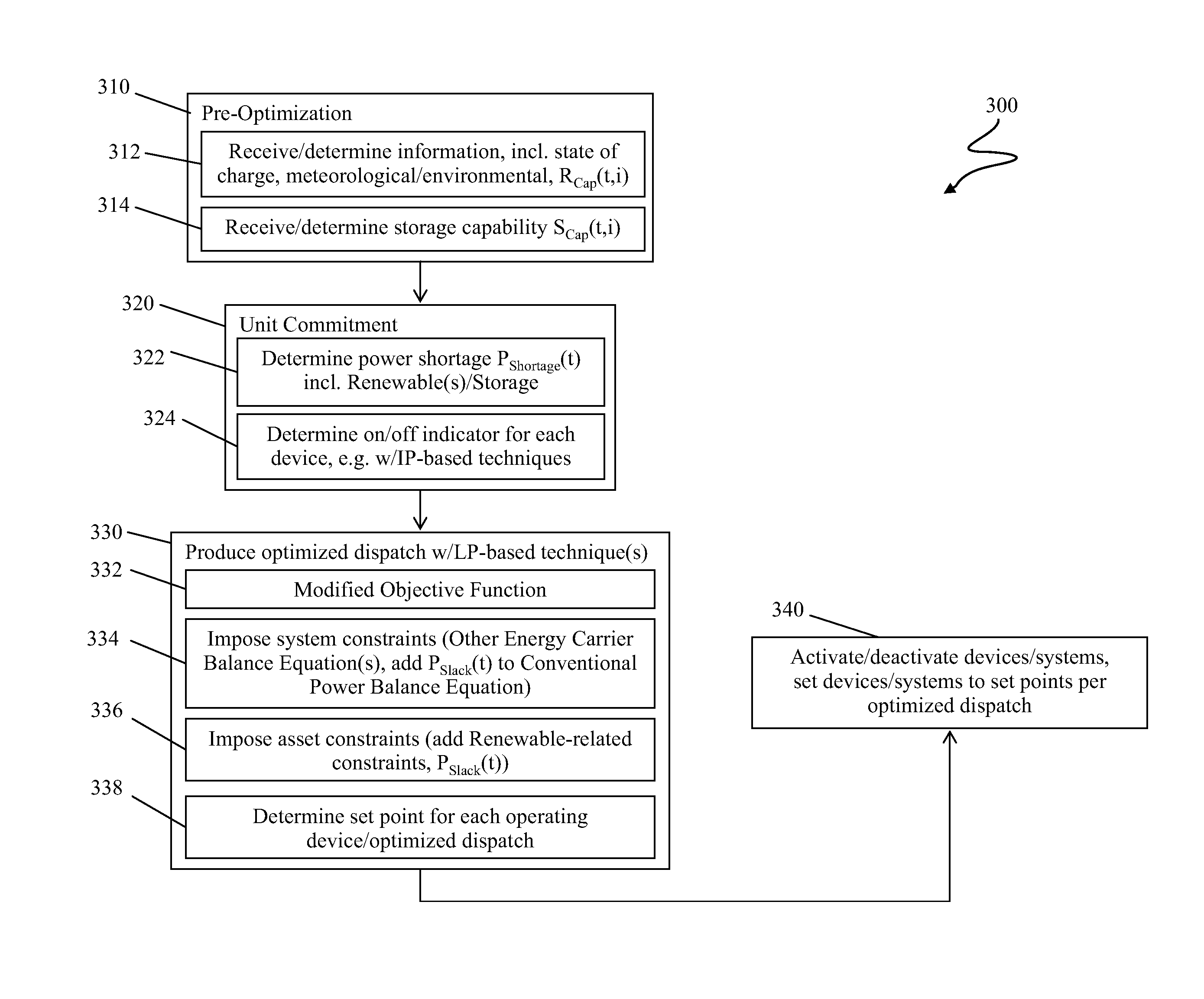
[0016]As indicated above, typical microgrid dispatch optimization techniques do not treat renewable power sources as isochronous sources. Rather, renewable sources are typically treated as stochastic sources with only forecasted power generation being taken into account due to strong fluctuations in power generation. However, some renewable power sources, such as hydroelectric power generators, are less intermittent and so may be operated in or treated as operating in an isochronous mode more often to meet microgrid operational constraints. Because renewable power generation sources may not provide a fixed upper bound of power generation in the manner that most non-renewable power generation sources do, a dispatch technique should be reformulated to consider such less-intermittent renewable power generation sources as isochronous sources.

[0017]Renewable sources may, for example, be categorized as dispatchable and non-dispatchable. Wind, solar, and hydroelectric renewable sources wit...


PUM


Abstract

A microgrid including a renewable power source is optimized by treating the renewable source as operating in an isochronous mode, and by decomposing the optimization process. A renewable capability is defined for the renewable source to enable treatment of the renewable source as operating in an isochronous mode. The renewable capability may be based on a power rating of the renewable source. An objective function of the microgrid optimization problem may then be optimized while treating the renewable source as operating in an isochronous mode. A penalty factor may be applied to avoid power shortage.

Description

BACKGROUND OF THE INVENTION[0001]The disclosure relates generally to power generation, and more particularly to optimization of power generation in a microgrid that includes at least one renewable power source.[0002]In power generation, it is becoming more common for power system assets to include a mixture of renewable and non-renewable power generation sources, particularly in so-called “smart grid” power generation and distribution. Particularly with regard to power systems including renewable energy sources, excess energy may be stored for use during times when power demand exceeds power generation capacity, though in a mixed-generation environment, non-renewable sources may be called upon instead of, or in addition to, stored energy. It is often desirable to optimize use of renewable, non-renewable, and stored energy resources so that they may be used more advantageously.[0003]Generation optimization techniques for microgrid applications typically use load and renewable power g...

Claims


Application Information

Patent Timeline
IPC IPC(8): G06F1/28
CPCH02J13/0013H02J2003/003H02J2003/007H02J3/382Y04S10/54Y02B90/2607Y02E40/72Y04S10/545Y04S40/12Y04S40/22Y02E40/76Y02E60/76Y04S10/123H02J3/003H02J2203/20H02J2300/20H02J3/381H02J13/00006Y02B90/20Y02E40/70Y02E60/00Y04S10/50Y04S40/20H02J3/466
Inventor ZADEH, MOHAMMAD REZA DADASHHAJIMIRAGHA, AMIRHOSSEINKROK, MICHAEL JOSEPH
Owner GENERAL ELECTRIC CO
Why Eureka
Try Eureka