Bayonet Mirror Mount

Inactive Publication Date: 2012-11-15
OLIVE TREE FINANCIAL GROUP
View PDF1 Cites 0 Cited by
  • Summary
  • Abstract
  • Description
  • Claims
  • Application Information

AI Technical Summary

Benefits of technology

[0007]The present invention is directed toward a mount for mounting a mirror on a knife having a blade, a blade tip and a handle. The mount has a base that is configured to engage the mirror, and a housing that is coupled with the base. The housing defines a cavity that is configured for receiving at least a portion of the knife blade such that the blade tip is substantially enclosed by the housing when the blade is positioned in the cavity. Preferably, the housing encloses portions of first and second edges of the blade that meet at the blade tip. Most preferably, the housing encloses approximately between 1 to 5 inches of the knife blade, including its edges, in addition to enclosing the blade tip. The housing preferably also engages a portion of the blade for retaining the housing on the blade. When the mirror mount is mounted on a knife, a user can extend the knife and mirror into a dangerous area and expand the user's field of view without exposing the user to harm.
[0008]Because the mirror mount substantially encloses the blade tip of a knife to which it is mounted, a user of the mount can quickly and safely mount the mirror mount to a knife without danger of cutting his or her hand on the knife blade. This feature is extremely advantageous for individuals facing dangerous life or death situations, such as military soldiers and police officers, because they can rely on and use the mount in a quick and safe manner.

Problems solved by technology

While the WWI mirror mount generally worked for its intended purpose, it did not allow a soldier to quickly and safely mount a mirror on a knife without danger of cutting his or her hand on the knife blade due to the fact that the mount did not substantially enclose the tip of a knife to which it was mounted.

Method used


Image

  • Bayonet Mirror Mount
  • Bayonet Mirror Mount
  • Bayonet Mirror Mount

Examples


Embodiment Construction

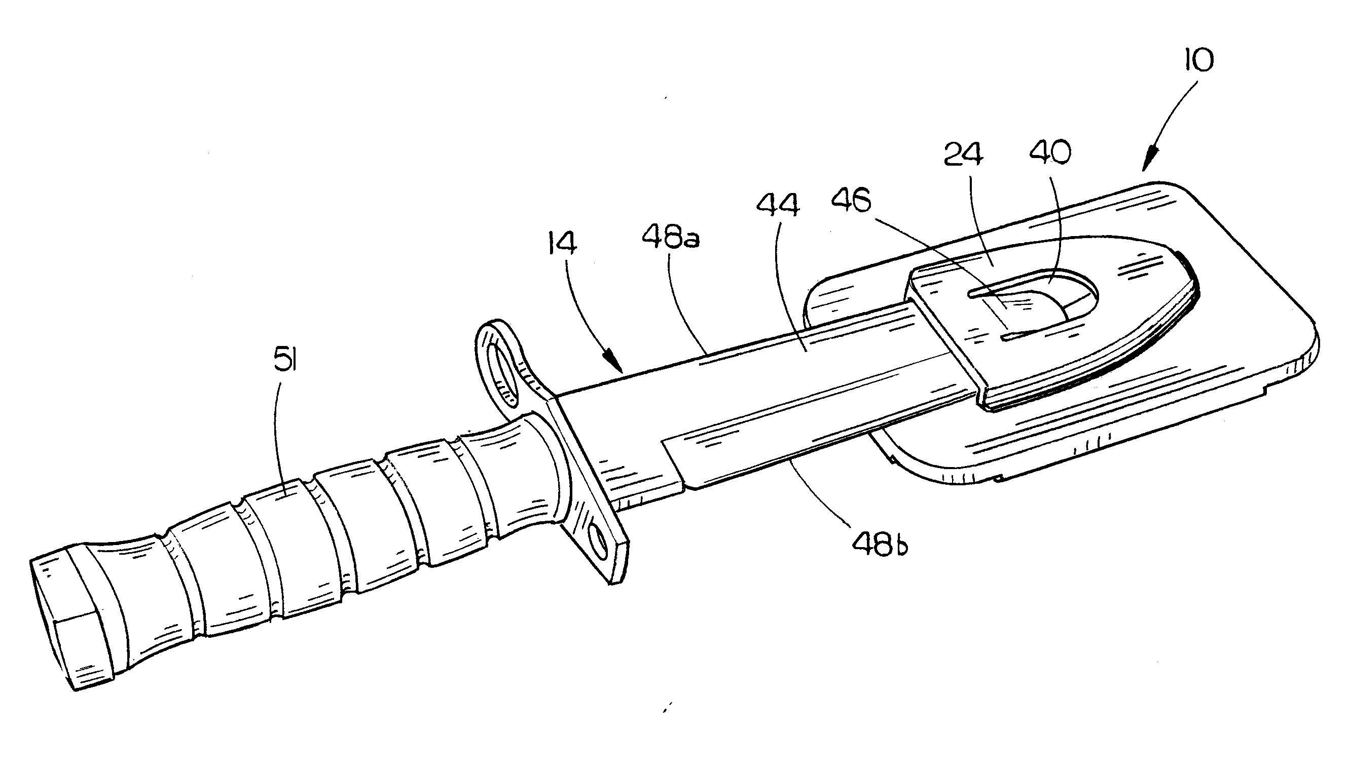
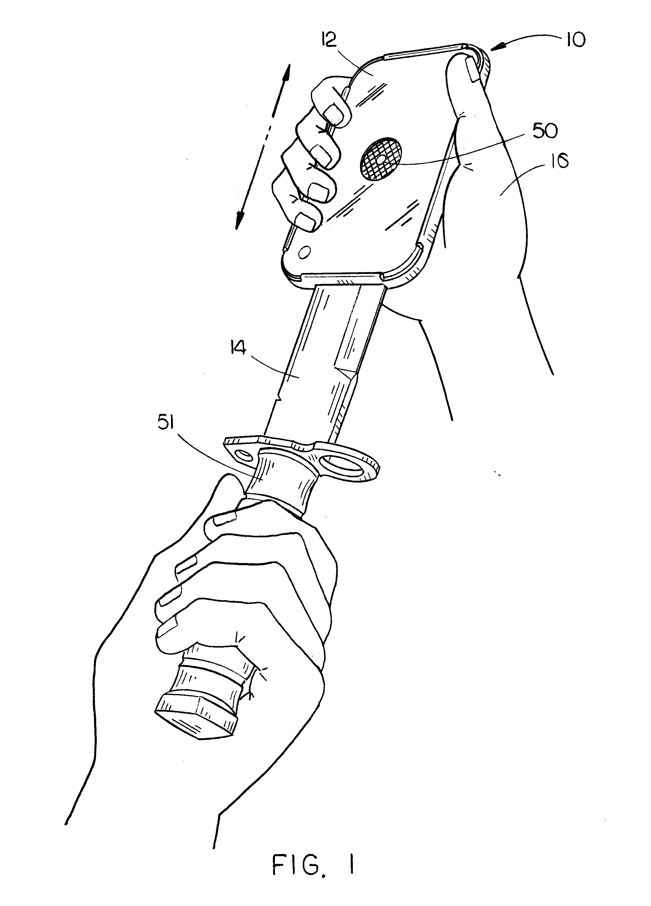
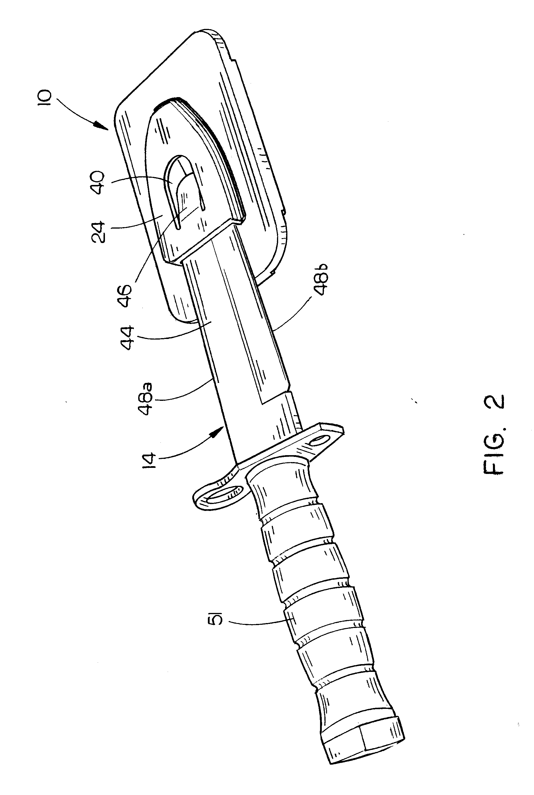
[0019]Referring to FIG. 1, an exemplary embodiment of a mount in accordance with the present invention is shown and designated by the reference numeral 10. The mount 10 engages a mirror 12 and has a housing structure, which is described in detail below, that receives a portion of a knife 14 for mounting the mirror 12 on the knife 14. Due to the structure of the mount 10 a user can safely grasp the mount 10 with his or her hand 16 and quickly engage or disengage the mount 10 with the knife 14 without danger of cutting his or her hand 16 on the knife 14. While the mount 10 is operable to be used with any type of knife 14, preferably the mount 10 is used with a bayonet that is operable to be mounted on a rifle. When the mount 10 is mounted on a bayonet which is mounted to a rifle, a user of the rifle can extend the bayonet, mount 10 and mirror 12 into a potentially dangerous area, such as around a corner or in a hole, and use the mirror 12 to enhance his or her field of view without en...


PUM


Abstract

A mount for mounting a mirror on a knife. The knife has a blade, a blade tip, and a handle. The mount has a base that is configured to engage a mirror, and a housing that is coupled with the base. The housing defines a cavity that is configured for receiving at least a portion of the knife blade such that the blade tip is substantially enclosed by the housing when the blade is positioned in the cavity. Preferably, the housing encloses approximately between 1 to 5 inches of the knife blade.

Description

CROSS-REFERENCE TO RELATED APPLICATIONS[0001]Not applicable.STATEMENT REGARDING FEDERALLY SPONSORED RESEARCH OR DEVELOPMENT[0002]Not applicable.BACKGROUND OF THE INVENTION[0003]1. Field of the Invention[0004]The present invention relates generally to a mount, and more particularly to a mount that is operable to mount a mirror on a knife.[0005]2. Description of Related Art[0006]A mirror mount that is capable of mounting a mirror on a knife was produced for use by soldiers during World War I. The mirror mount allowed a soldier to mount a mirror on a knife or bayonet for the purpose of extending the mirror into a dangerous area and expanding the soldier's field of view without exposing the soldier to harm. While the WWI mirror mount generally worked for its intended purpose, it did not allow a soldier to quickly and safely mount a mirror on a knife without danger of cutting his or her hand on the knife blade due to the fact that the mount did not substantially enclose the tip of a knif...

Claims


Application Information

Patent Timeline
IPC IPC(8): G02B7/182
CPCF41C27/18G02B7/182
Inventor SCHULTZ, GREGORY RUSSELL
Owner OLIVE TREE FINANCIAL GROUP
Why Eureka
Try Eureka