Universal canopy suspension system

a suspension system and universal technology, applied in ventilation systems, lighting and heating apparatus, heating types, etc., can solve the problems of finding one to meet the exact needs of users, and achieve the effect of convenient transportation, adequate top-down air flow, and ease and simplicity

Active Publication Date: 2012-11-15
CANOPY BREEZES
View PDF29 Cites 6 Cited by
  • Summary
  • Abstract
  • Description
  • Claims
  • Application Information

AI Technical Summary

Benefits of technology

[0004]The advantage of the Universal Canopy Suspension System is that it provides comfort to the user of any canopy-styled tent from the outdoor elements (cold temperatures, hot temperatures or darkness) with ease and simplicity. This system provides the user with the ability to perform other activities while enjoying a climate-controlled environment. The system is easy to transport, going from an easy-to-tote bag to installation in minutes. It is not heavy but large enough to provide adequate top down air-flow or evenly distributed heat as well as plentiful lighting. The suspension system is able to provide lighting and heating instead of or in combination with the fan. Its blades for the fan are made of a foam, or like materials which makes it safe, durable, and weather resistant. A latex dipping process keeps my prototype's blades stiffer which provide better air flow. My blades are not limited to foam with a latex cover, similar production options are presently being explored including injection molding and sprayed on finishes. The Universal Canopy Suspension System and its embodiments also function properly and easily attach to the largest canopy-styled tents as well as those smaller canopy-styled tents with thin poles that are used for recreational purposes, even if the ground on which the canopy-styled tent is to be erected is uneven. It is quiet and out-of-the-way of the participants, freeing them to enjoy activities with comfort and convenience. My Universal Canopy Suspension System also has the ability to be manufactured and shipped to user complete with their blade color of choice I am exploring the idea for the user to have the ability order and change his / her blades without compromising the fan's weather resistant characteristic. This method of exchange will be safe, simple, and quick. This will also give the user the ability to replace a damaged blade. Another advantage of the Universal Canopy Suspension System is simple cleaning By quickly removing the fan from the canopy pole(s), a user is in a better position to clean the fan safely and efficiently. A damp rag across the entire surface of the fan can be quickly performed after each use. Having the ability to unplug the fan from its power source prior to cleaning alleviates the risk of shock. The extra step of ladders and other means for removing the suspension system can be avoided by the ability of some canopy-styled tents to adjust its leg length to lower its canopy or roof can also be avoided. Screwdrivers or similar devices used for the removing of a fan's cover to clean is also avoided with my Universal Canopy Suspension System. The latex, or like material, covering the blades prevents dirt and finger prints being embedding to the porous blade's surface. Current design and manufacturing changes to make my Universal Canopy Suspension System and its embodiments battery powered are being explored. Types of batteries to meet our needs of RPMs and extended battery life are available on the market. Finding one to meet those exact needs are a challenge.
[0007]The fan 34 connects to the down rod 40, by incursion of the said down rod 40 into the top female cap of the fan 23 and locked into place with a double button snap. To decrease the height of the fan an extension pole 18 can be attached between the down rod 40 and the female cap 20 on top of the fan. The blades 28 of the fan 34 are made of shaped foam dipped in latex. Sure this is not the only way to make these blades 28, but this process worked well for our prototypes. The blades 28, attached to a blade wheel 56, are thick enough and rigid enough to keep their shape and provide efficient airflow. At the base 54 of the fan 23 can also have a light. The fan and light can be controlled via the remote control 92. This and additional embodiments are powered by normal US extension cords or socket 58 or by an optional battery.
[0011]There is not just one way to connect my Universal Canopy Suspension System's bracket: ropes, tape, bungee cords, pin and clips, and the like are a few options. My goal is to make the bracket and its snap on embodiments simple to assemble and functional. FIG. 19 is another very simplistic method of design and connection of the bracket. The arms on each of the attachment bracket each have a hook on each arm. These hooks are similar to the Christmas wreath holders that can be installed above the door of a house. There are four hooks in FIG. 19; however there could be only one, two or more. This design of the Universal Canopy Suspension System's bracket allows the user to simply push the four hooks of the attachment bracket between the poles and up towards the canopy. Once the base of the hooks are above the canopy's poles, twist the attachment bracket (counter clockwise with this CAD design) until the bracket is stopped by the canopy's poles. At this point the hook should be aligned so that one may release or pull down on the bracket locking it into place. This is a much easier method and keeps the hook and loop threading out of the picture. This design is to be further explored, but I feel it is a viable design option for my Universal Canopy Suspension System's bracket. As far as the drop down pole with ball joint, its locking mechanism, the oval 18 and arm integrity ridges 48, I do not see a need for design altering at this point. The attachment bracket will connect faster to the canopy's poles and hold the bracket and its connected embodiment without issues.

Problems solved by technology

Finding one to meet those exact needs are a challenge.

Method used


Image

  • Universal canopy suspension system
  • Universal canopy suspension system
  • Universal canopy suspension system

Examples


Embodiment Construction

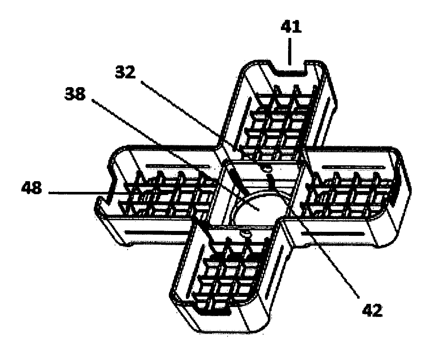
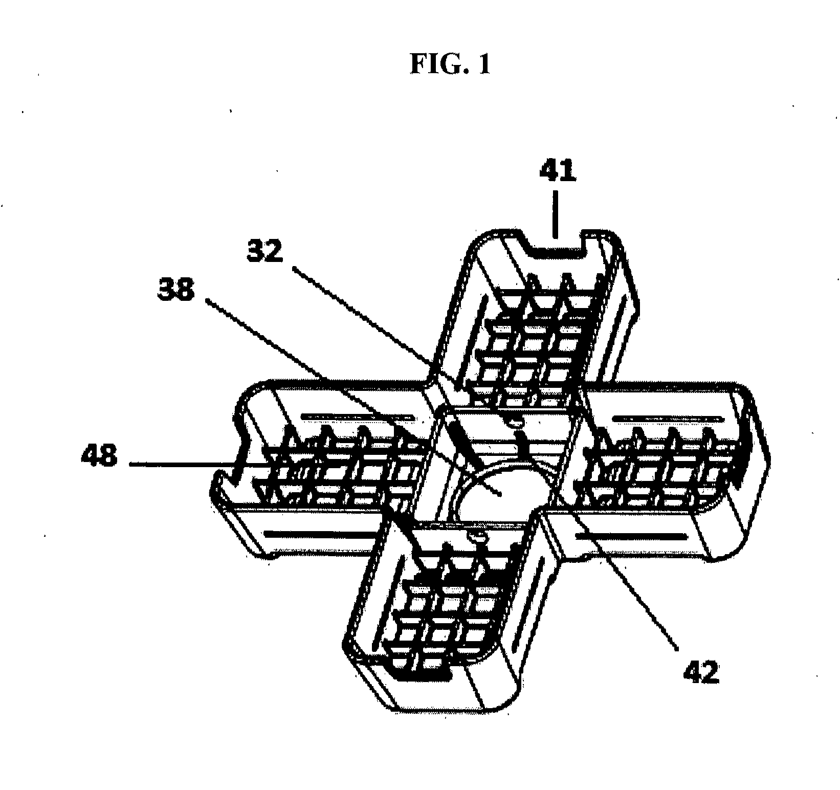
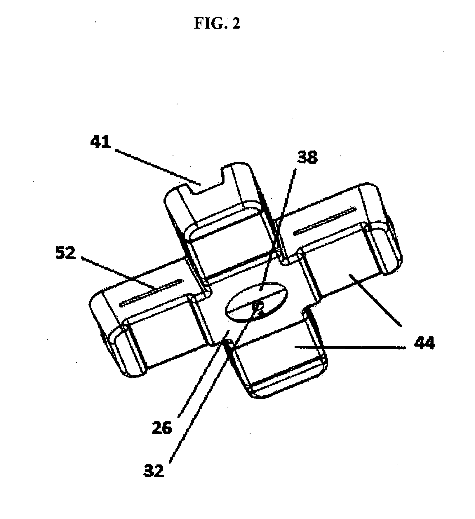
[0012]18 extension pole for height adjustment[0013]20 motor housing unit's universal female cap, connects to extension pole or directly to the downrod[0014]22 extension pole's hole for the double locking button snap, attaches to downrod or pin and clip with a ceiling plug[0015]23 hole in motor housing unit's female cap for double locking button snap, pin and clip, or other locking mechanism[0016]25 downrod's hole(s) at the base of ball joint that allows double locking button snaps to connect directly to an attachment pole or to the female cap of fan, light, or heater[0017]26 attachment bracket[0018]28“soft to the touch” blade made from flexible foam and latex or similar materials that allows shaping and bending without breaking[0019]32 attachment bracket's hole for security pin insertion[0020]33 security pin and clip (clip not shown) inserted through the ball joint and downrod of attachment bracket[0021]34 upper housing unit for motor[0022]38 downrod's oval hole[0023]39 cut out to a...


PUM


Abstract

A suspension system for the attachment of a multiple bladed fan, connected beneath the roof of a canopy-styled tent or other overhead structure. The system's bracket is comprised of multiple arms that universally grip the frame of the said canopy-styled tent or overhead structure. Suspension is not limited to a fan, but also other embodiments, each powered by a plug or battery. The bracket is manufactured in polymer or like material. The system's fan blades are comprised of foam, rubber, or other soft matter. The suspension system allows the fan or other attached embodiment's height to be manipulated by a process further shown in this application. The system further includes embodiments for lighting, heating, or the mounting of additional embodiments. The suspension system and its embodiments are portable and may be broken down into a self-contained bag or case for easy transport.

Description

CROSS-REFERENCE TO RELATED APPLICATIONS[0001]This application claims the benefit of my previously submitted utility PPA, Application No. #61 / 518,624, with Filing or 371(c) date of May 9, 2001.FIELD OF INVENTION[0002]This application relates to the use of an attachable fan and its embodiments to an outdoor canopy-styled tent.BACKGROUND OF PRIOR ART[0003]Canopy-styled tents have multiple legs, a roof, and sometimes side walls. They have been used for hundreds of years as shelter; however, they are limited in providing comfort and protection for the individual user from the outdoor elements such as extreme temperatures or poor lighting. Another problem is that some current products do not free up the user to perform other tasks while enjoying the climate-controlled atmosphere. For example, battery powered hand-held fans are currently available for purchase. Some of the hand-held fans are inexpensive and safe, yet they do not easily solve this problem. There are currently free standing ...

Claims


Application Information

Patent Timeline
Patent Type & Authority Applications(United States)
IPC IPC(8): F16M13/02
CPCF24F7/007F24F13/32
Inventor ARNOLD, III, FRANK STEELE
Owner CANOPY BREEZES
Why Eureka
Try Eureka