Multi-band compatible multi-antenna device and communication equipment

a multi-antenna and communication equipment technology, applied in the direction of antenna details, antennas, electrical equipment, etc., can solve the problem that the miniaturization of the miniaturized antenna cannot be achieved, and achieve the effect of reducing the interconnection amount, reducing the amount of interconnection between the first antenna element and the second antenna element, and reducing the distance between the antenna elements

Active Publication Date: 2012-11-15
FUNAI ELECTRIC CO LTD
View PDF4 Cites 37 Cited by
  • Summary
  • Abstract
  • Description
  • Claims
  • Application Information

AI Technical Summary

Benefits of technology

[0042]In the multi-band compatible communication equipment according to the fourth preferred embodiment of the present invention, by providing a single passive element which resonates at both the frequency corresponding to the first frequency band and the frequency corresponding to the second frequency band between the first antenna element and the second antenna element as described above, it is possible to reduce the amount of interconnection between the antenna elements. In addition, because the amount of interconnection between the first antenna element and the second antenna element can be reduced, the distance between the antenna elements can be correspondingly reduced and, as a result, it is possible to miniaturize the multi-band compatible multi-antenna device.
[0043]Consequently, in accordance with the above described preferred embodiments, miniaturization of the communication equipment itself including such a multi-band compatible multi-antenna device is also possible. Accordingly, this communication equipment can be miniaturized by reducing the distance between the antenna elements. Preferred embodiments of the present invention are particularly effective for communication equipment in relation to which there is a demand for miniaturization such as, for example, with mobile phones.

Problems solved by technology

However, with the multi-band compatible MIMO antenna of Japanese Patent Application Laid-Open Publication No. 2008-29001, while different frequency bands can be handled by switching the full length of each antenna element using switching control, there is a problem in that the MIMO antenna cannot be miniaturized because the distance between the antenna elements needs to be large so as to reduce an amount of the interconnection between the antenna elements.

Method used


Image

  • Multi-band compatible multi-antenna device and communication equipment
  • Multi-band compatible multi-antenna device and communication equipment
  • Multi-band compatible multi-antenna device and communication equipment

Examples


first preferred embodiment

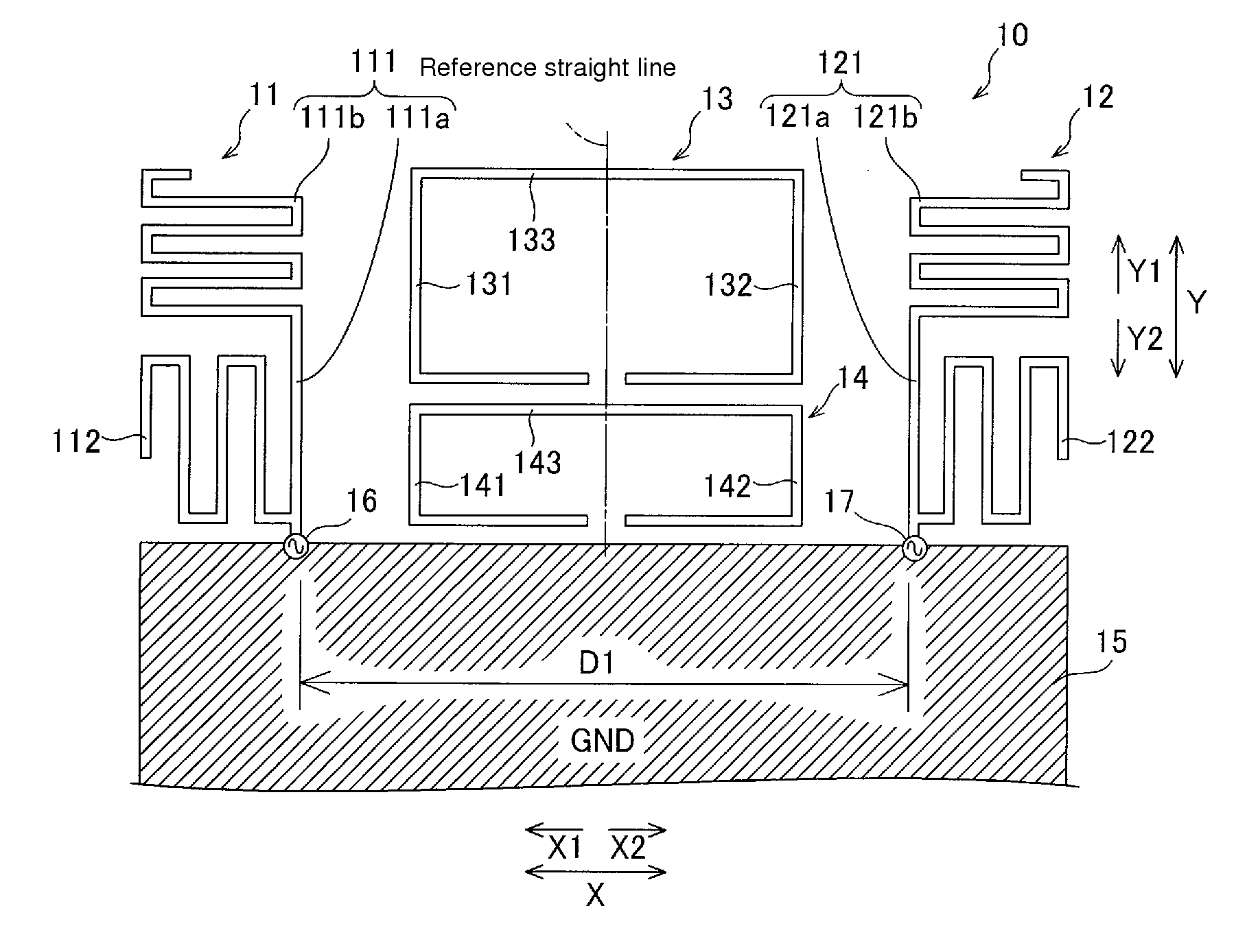
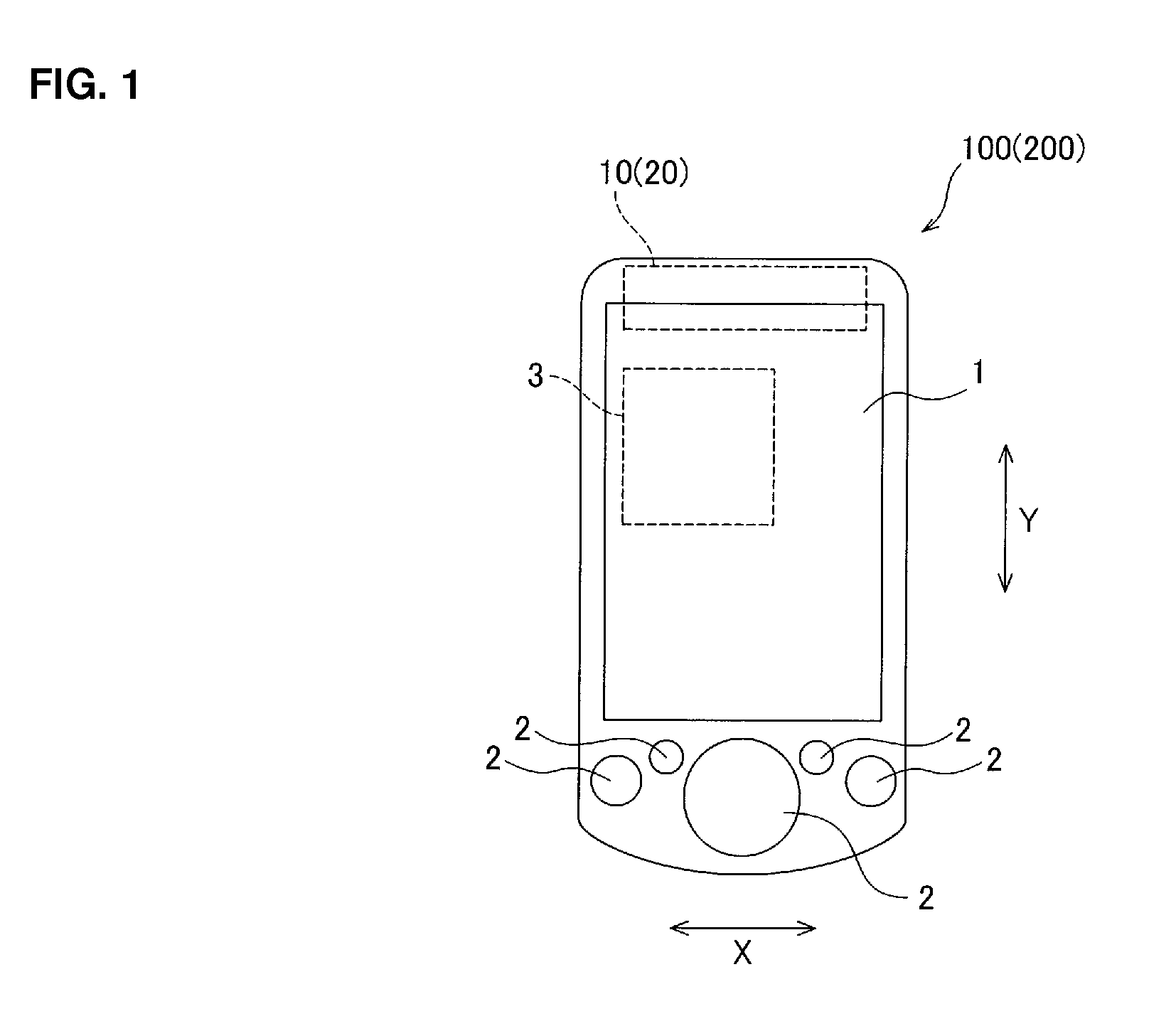
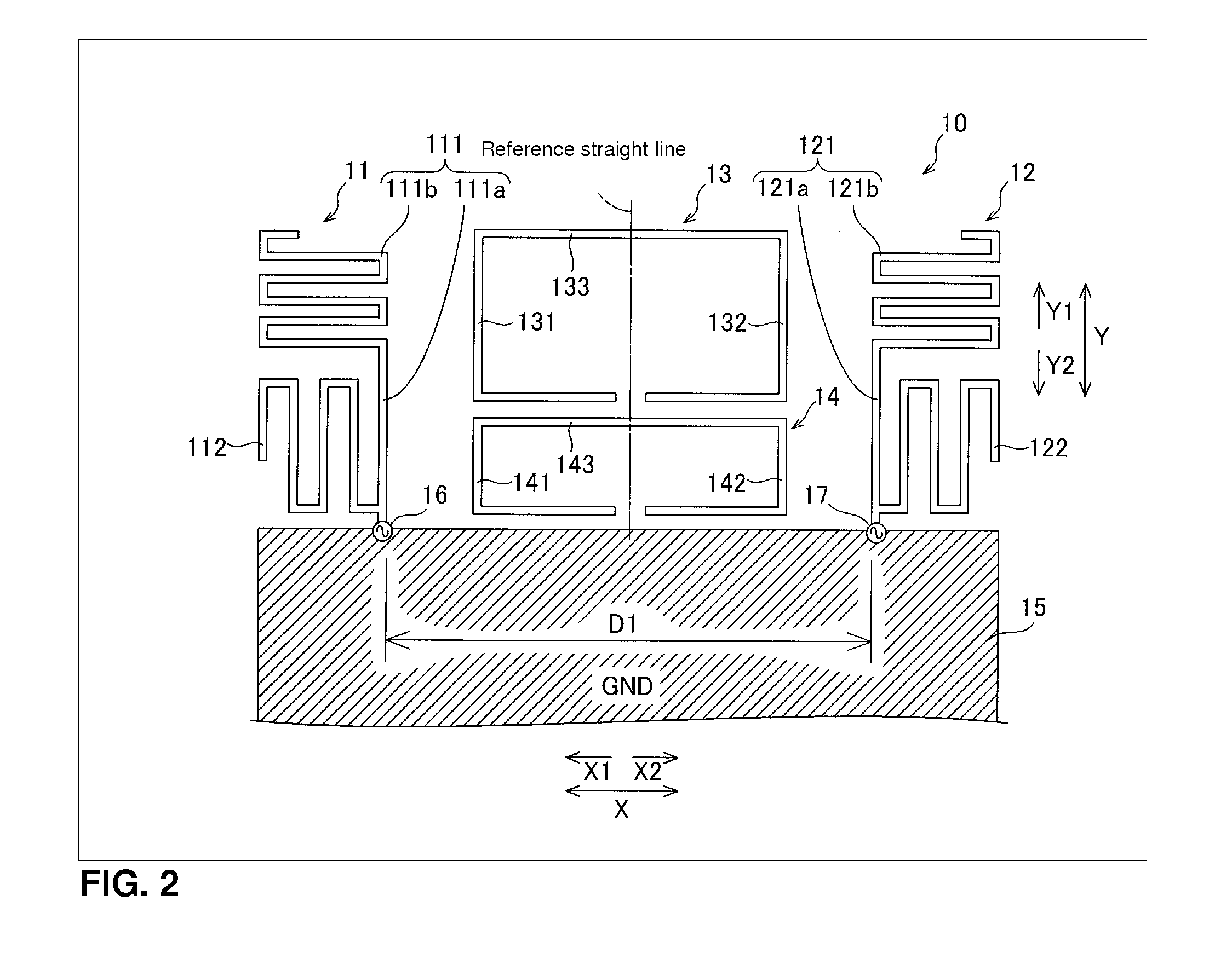
[0078]First, the configuration of the mobile phone 100 according to a first preferred embodiment of the present invention will be described with reference to FIGS. 1 and 2. Note that in the first preferred embodiment, an example will be described in which the multi-antenna device 10 of the present invention is applied to the mobile phone 100 which is used as the communication equipment.

[0079]As is shown in FIG. 1, the mobile phone 100 according to the first preferred embodiment of the present invention includes a display screen portion 1 and operating portions 2. Furthermore, a communication portion 3 and a multi-band compatible multi-antenna device 10 are provided inside the housing of the mobile phone 100.

[0080]The display screen portion 1 is preferably provided by a liquid crystal display and is configured so as to be able to display images. The operating portions 2 are preferably defined by, for example, a plurality of buttons, touch pads, etc. and are configured to be able to r...

second preferred embodiment

[0109]Next, referring to FIG. 6, a description will be given regarding the multi-antenna device 20 of the mobile equipment 200 (see FIG. 1) according to a second preferred embodiment of the present invention. In this second preferred embodiment, unlike the aforementioned first preferred embodiment in which the first passive element 13 and the second passive element 14 are both provided substantially in the shape of the letter C, a configuration will be described in which a first passive element 23 and a second passive element 24 are both arranged so as to extend in the X direction while being folded in the Y direction. Note that in the second preferred embodiment, an example will be described in which the multi-antenna device 20 of the present invention is applied to the mobile phone 200 which is used as the communication equipment.

[0110]The multi-band compatible multi-antenna device 20 of the mobile equipment 200 (see FIG. 1) according to the second preferred embodiment of the pres...

third preferred embodiment

[0140]First, the configuration of the mobile phone 100 according to a third preferred embodiment of the present invention will be described with reference to FIGS. 1 and 17. Note that in the third preferred embodiment, an example will be described in which the multi-antenna device 10 of the present invention is applied to the mobile phone 100 which is used as the communication equipment.

[0141]As is shown in FIG. 1, the mobile phone 100 according to the third preferred embodiment of the present invention includes a display screen portion 1 and operating portions 2. Furthermore, a communication portion 3 and a multi-band compatible multi-antenna device 10 are provided inside the housing of the mobile phone 100.

[0142]The display screen portion 1 is preferably provided by a liquid crystal display and configured so as to be able to display images. The operating portions 2 are preferably provided by, for example, a plurality of buttons, touch panels, etc. and are configured so as to be ab...


PUM


Abstract

A multi-band compatible multi-antenna device which is miniaturized by reducing a distance between antenna elements includes a first antenna element corresponding to a 1.5 GHz band and a 2.0 GHz band, a second antenna element corresponding to the 1.5 GHz band and the 2.0 GHz band, a first passive element which is arranged between the first antenna element and the second antenna element and which resonates at a frequency corresponding to the 1.5 GHz band, and a second passive element which is arranged between the first antenna element and the second antenna element separately from the first passive element and which resonates at a frequency corresponding to the 2.0 GHz band.

Description

BACKGROUND OF THE INVENTION[0001]1. Field of the Invention[0002]The present invention relates to a multi-band compatible multi-antenna device and communication equipment, and more specifically to a multi-band compatible multi-antenna device including a plurality of antenna elements and communication equipment including such a multi-band compatible multi-antenna device.[0003]2. Description of the Related Art[0004]Multi-band compatible multi-antenna devices including a plurality of antenna elements have been conventionally known (see Japanese Patent Application Laid-Open Publication No. 2008-29001, for example).[0005]The aforementioned Japanese Patent Application Laid-Open Publication No. 2008-29001 discloses a multi-band compatible MIMO antenna (multi-antenna device) including two antenna elements. Each of the antenna elements of this MIMO antenna includes a first radiating plate, a second radiating plate, and a PIN diode that can electrically link the first radiating plate and the s...

Claims


Application Information

Patent Timeline
Patent Type & Authority Applications(United States)
IPC IPC(8): H01Q21/30
CPCH01Q1/243H01Q5/371H01Q21/28H01Q1/521H01Q5/392
Inventor AIZAWA, DAISUKE
Owner FUNAI ELECTRIC CO LTD
Why Eureka
Try Eureka