Temporary and / or emergency lighting system with inflatable bearing structure

Active Publication Date: 2012-11-15
KOTHARI MANISH
View PDF4 Cites 6 Cited by
  • Summary
  • Abstract
  • Description
  • Claims
  • Application Information

AI Technical Summary

Benefits of technology

[0018]The blower on this device will supply a steady stream of air to inflate the tube that supports the light. Unfortunately, one of the effects of constant blower operation is the production of noise. A noise dampening device will be installed on the bottom of the blower motors. The housing will fit over the blower motor and will be insulated to provide noise reduction. A hole will be placed on the sides of the housing that will permit the air to f

Problems solved by technology

The Medici patent uses a plurality of guide wires to stabilize the light source bu

Method used


Image

  • Temporary and / or emergency lighting system with inflatable bearing structure
  • Temporary and / or emergency lighting system with inflatable bearing structure
  • Temporary and / or emergency lighting system with inflatable bearing structure

Examples


Example

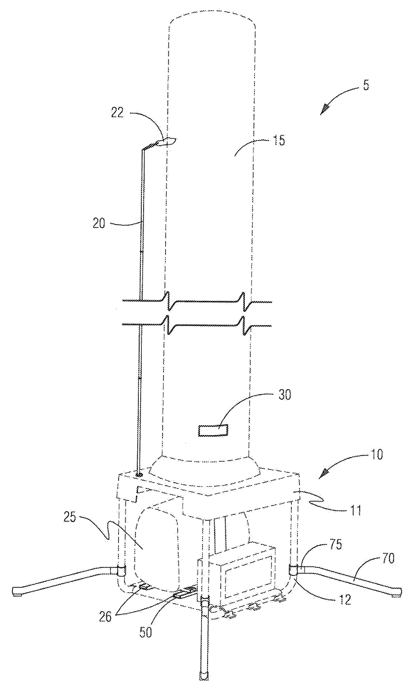
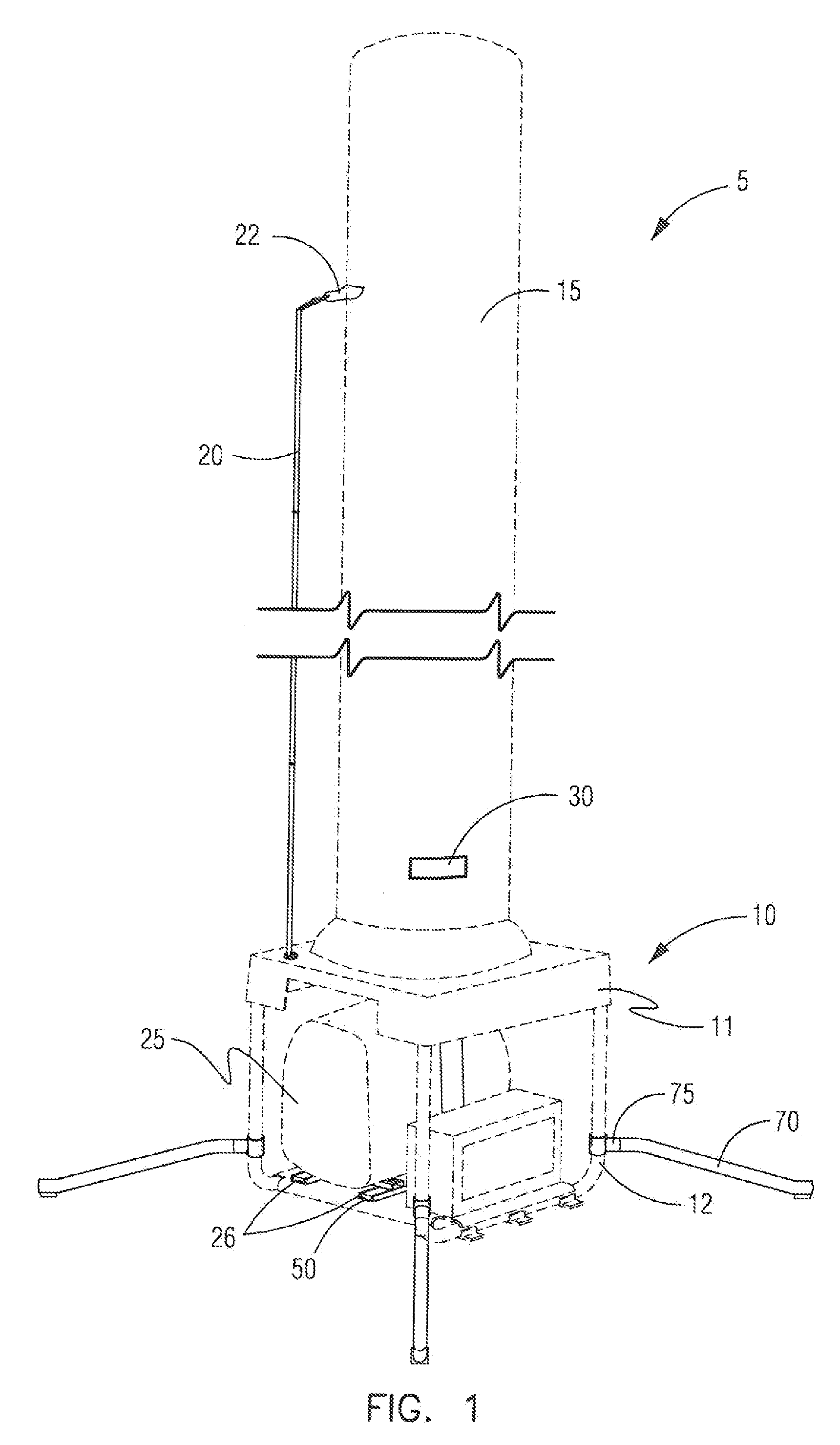
[0059]This device is intended to be a portable light source. This device may be used in extreme conditions either on land or at sea. It is designed to provide sufficient lighting during times of extreme conditions.

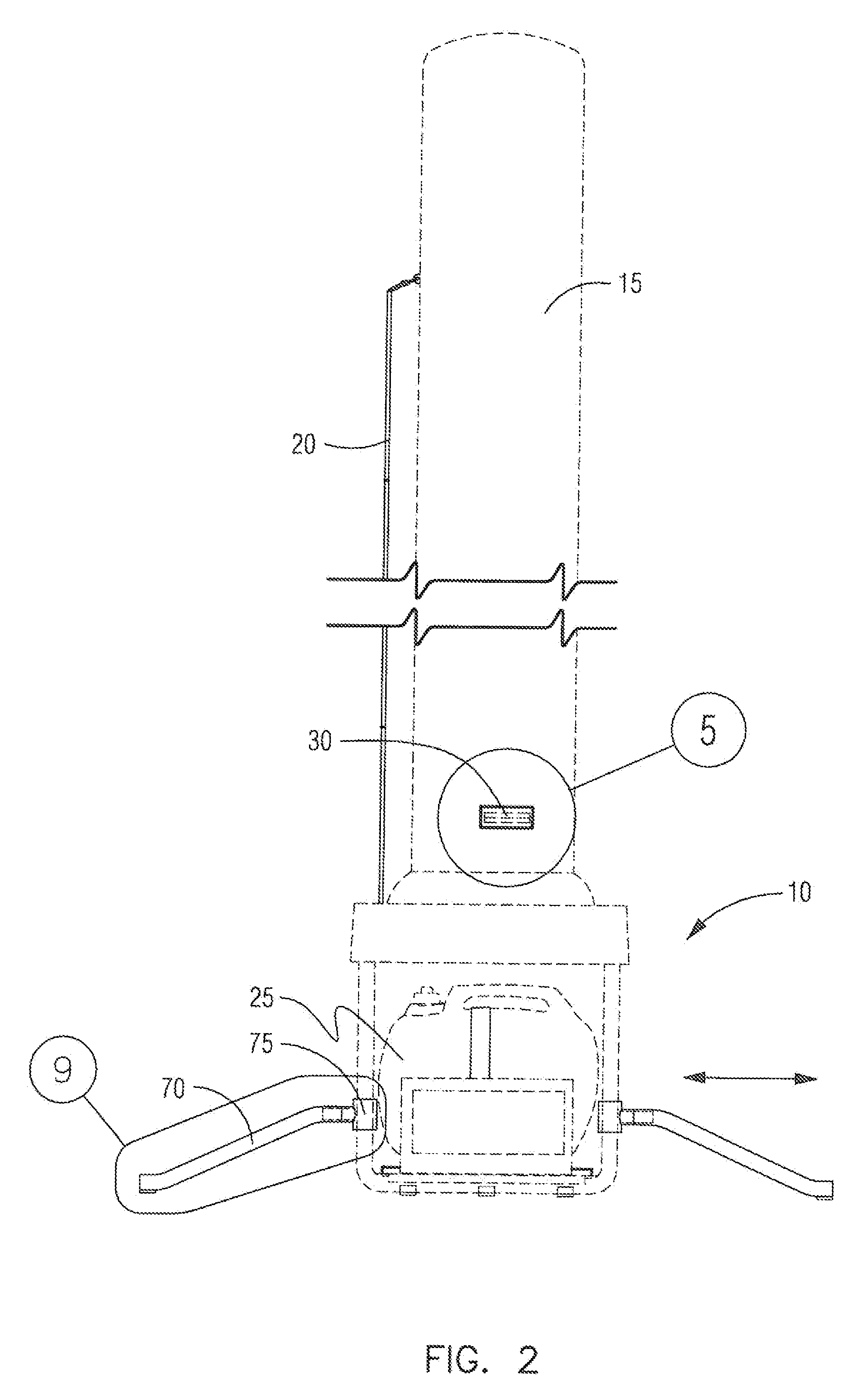
[0060]The device 5 will be comprised of a base member 10 on top of which is mounted an inflatable light structure 15, which is likely to be opaque in order to provide the necessary amount of lighting for any given condition. The light structure 15 will of a predetermined height or length and likely cylindrical and different lengths may be used.

[0061]The light structure 15 is likely to be of a synthetic material, although a variety of other materials may be used. In the light structure 15 will be a light (not depicted) secured to the interior of the tube. The tube should be able to withstand extreme conditions and should be strong enough for those conditions. Although many different materials may be used for the light structure and no specific material is being claimed, the...


PUM


Abstract

In order to provide a temporary lighting solution in extreme weather or lighting conditions, this application has been conceived. A set of blowers will continuously operate to inflate a long cylindrical tube in which a light has been placed to illuminate a designated area. Because the unit may be used outdoors a stabilizing rod has been placed in the event of a sudden loss of power to prevent the tube from deflating rapidly and descending rapidly to the ground level and causing possible injury to persons on the ground or the light itself. Because this device may be used in extremely windy conditions, a plurality of outriggers will attach to the frame and extend outward to stabilize the device, when needed. Because the blowers will operate continuously and thereby produce noise a plurality of noise abatement containers are placed around the blowers to help lessen the noise level.

Description

RELATED TO OTHER APPLICATIONS[0001]This is a continuation in part of a pending application that was filed on Aug. 20, 2010 and assigned Ser. No. 12 / 860,230. The undersigned wishes to take advantage of the filing date for the earlier application.BACKGROUND OF THE INVENTION[0002]A. Field of the Invention[0003]This relates to portable sources of light, particularly light that needs to be spread over a wide range, but only on a temporary basis. The device can be used in a variety of environments and is expected to be subjected to extremes in conditions.[0004]B. Prior Art[0005]There is one other prior art reference that is closely related to the current application and is found at Medici, U.S. Pat. No. 6,322,230. This current patent application improves on the Medici patent by adding a guiding or stabilizing rod to insure that the light source remains constantly in place and prevents the swaying of the light during windy conditions. Additionally, in the event of a sudden loss of power th...

Claims


Application Information

Patent Timeline
IPC IPC(8): F21L13/00
CPCF21L13/00F21V3/026F21V29/20F21W2131/10F21V29/83F21V21/06
Inventor KOTHARI, MANISH
Owner KOTHARI MANISH
Why Eureka
Try Eureka