Wafer dividing method

a technology of dividing method and dividing chip, which is applied in the direction of manufacturing tools, welding/soldering/cutting articles, metal working apparatuses, etc., can solve the problems of degrading generating debris on the side surface of each device chip obtained, etc., to prevent the degradation of the quality of each device and eliminate the possibility of trouble

Active Publication Date: 2012-11-15
DISCO CORP
View PDF5 Cites 40 Cited by
  • Summary
  • Abstract
  • Description
  • Claims
  • Application Information

AI Technical Summary

Benefits of technology

The present invention is about a method for preventing debris from affecting the quality of semiconductor devices. The method involves attaching an adhesive tape to the wafer, expanding the adhesive tape to divide the wafer, and heating the adhesive tape to catch any debris generated on the side surface of each device chip. This prevents debris from causing damage to the front side of each device and improves the overall quality of the semiconductor devices.

Problems solved by technology

The patent text discusses a problem in the process of making semiconductor devices. Cutting through the semiconductor wafer to create separate devices is difficult because the material is hard and brittle. To solve this problem, researchers have been exploring the use of a laser processing apparatus. This method involves applying a laser beam to the wafer along division lines to create modified layers that can be easily separated using an external force. This technique helps to reduce cutting debris and allows for smaller division lines, resulting in more efficient device fabrication.

Method used


Image

  • Wafer dividing method
  • Wafer dividing method
  • Wafer dividing method

Examples


Embodiment Construction

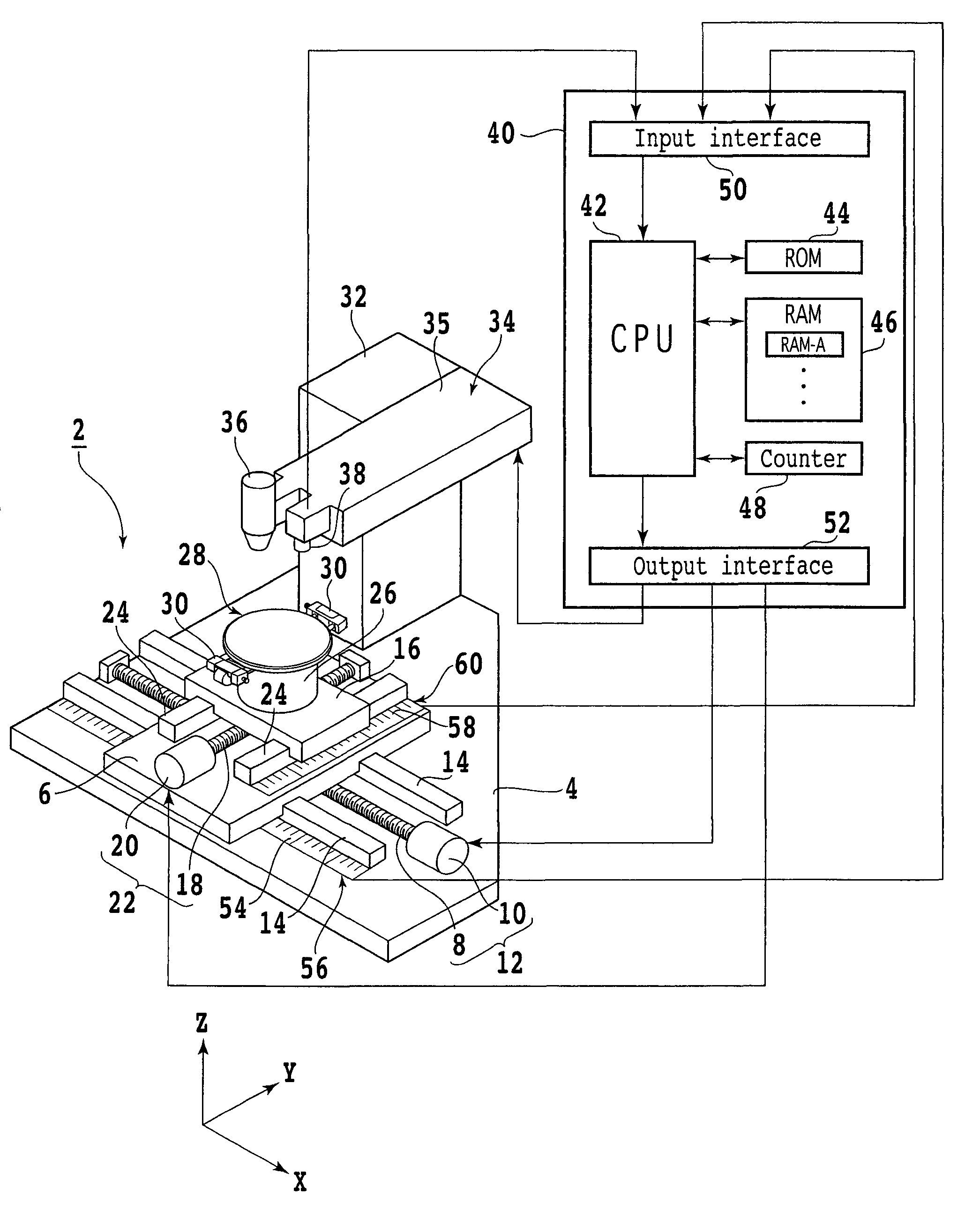
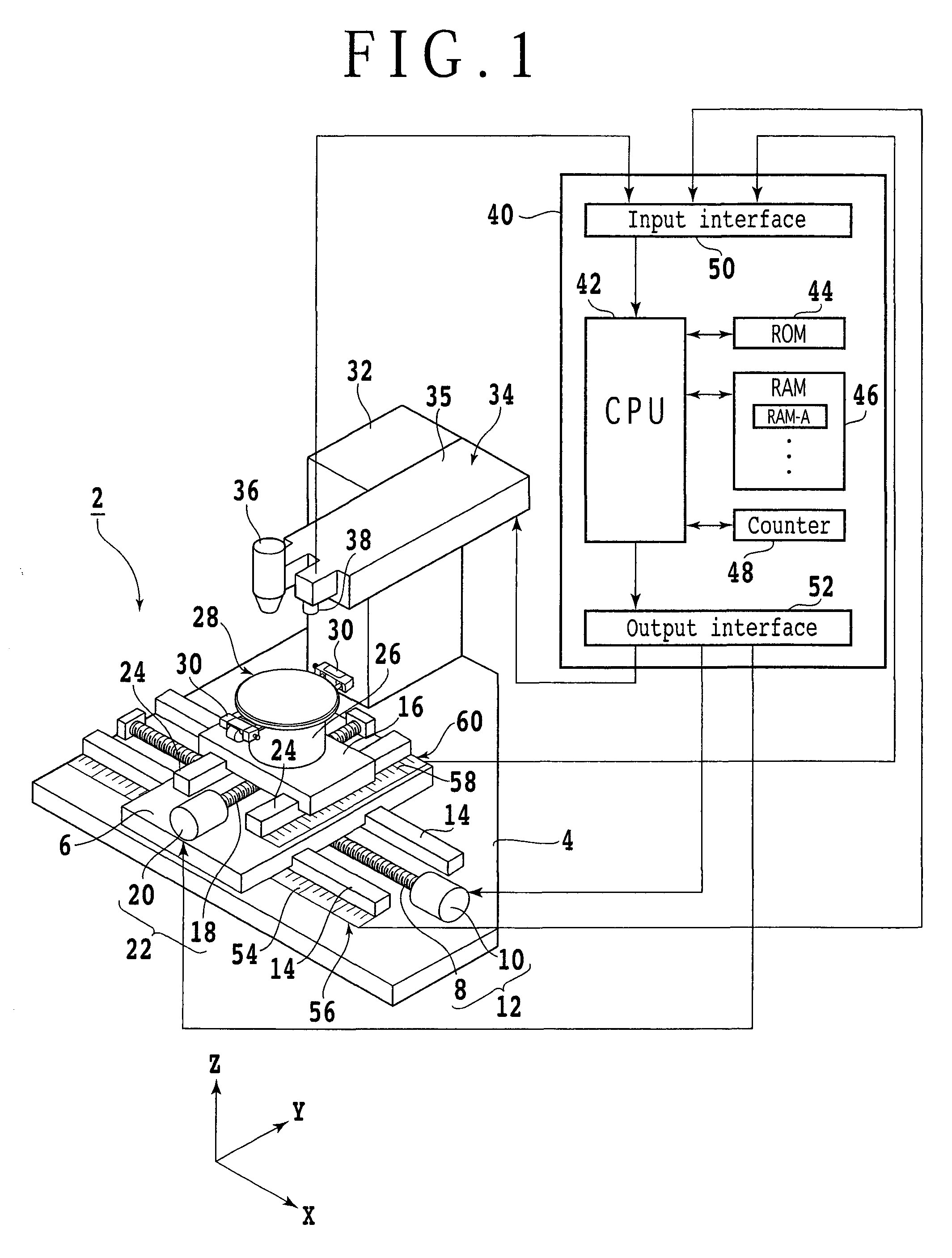
[0019]A preferred embodiment of the present invention will now be described in detail with reference to the drawings. FIG. 1 is a schematic perspective view of a laser processing apparatus 2 for performing the wafer dividing method according to the present invention. The laser processing apparatus 2 includes a stationary base 4 and a first slide block 6 supported to the stationary base 4 so as to be movable in the X direction shown by an arrow X. The first slide block 6 is movable in a feeding direction, i.e., in the X direction along a pair of guide rails 14 by feeding means 12 including a ball screw 8 and a pulse motor 10.

[0020]A second slide block 16 is supported to the first slide block 6 so as to be movable in the Y direction shown by an arrow Y. The second slide block 16 is movable in an indexing direction, i.e., in the Y direction along a pair of guide rails 24 by indexing means 22 including a ball screw 18 and a pulse motor 20. A chuck table 28 is supported through a cylindr...


PUM


Abstract

A wafer dividing method including a step of applying a laser beam to a wafer along division lines with the focal point of the laser beam set inside the wafer, thereby forming modified layers inside the wafer along the division lines; a step of attaching an adhesive tape to the wafer, the adhesive tape having a base sheet and an adhesive layer; a dividing step of applying an external force to the wafer by expanding the adhesive tape, thereby dividing the wafer along the division lines to obtain a plurality of device chips; and a debris catching step of heating the adhesive tape to thereby soften the adhesive layer such that it enters the space between any adjacent ones of the device chips obtained by the dividing step, thereby catching debris generated on the side surface of each device chip in the dividing step to the adhesive layer by adhesion.

Description


Claims


Application Information

Patent Timeline
Owner DISCO CORP
Why Eureka
Try Eureka