Image display system, image display apparatus and calibration method

a technology of image display and display system, applied in the direction of instruments, static indicating devices, etc., can solve the problem of huge time taken to carry out calibration, and achieve the effect of suppressing the time required

Active Publication Date: 2012-11-22
CANON KK
View PDF4 Cites 21 Cited by
  • Summary
  • Abstract
  • Description
  • Claims
  • Application Information

AI Technical Summary

Benefits of technology

[0015]According to the present invention, it becomes possible to suppress the time required to carry out calibration from becoming

Problems solved by technology

In the calibration described in the official gazette of Japanese patent application laid-open No. 2006-145798, the calibration is carried out with respect to all the levels of luminance

Method used


Image

  • Image display system, image display apparatus and calibration method
  • Image display system, image display apparatus and calibration method
  • Image display system, image display apparatus and calibration method

Examples


first embodiment

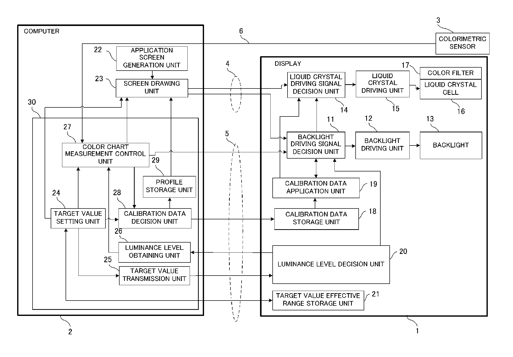
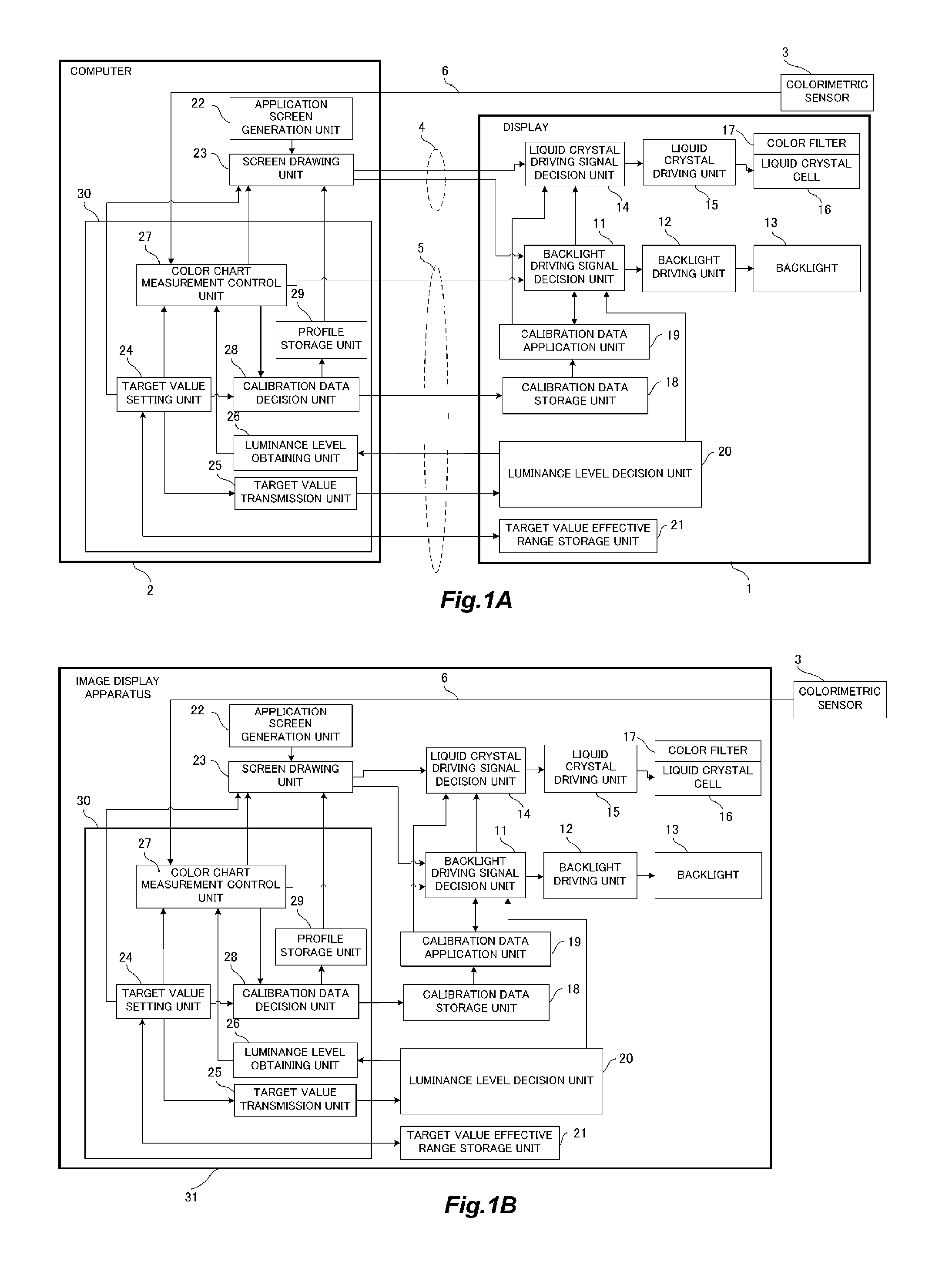
[0026]FIG. 1A is a construction diagram of an image display system according to a first embodiment of the present invention. A color liquid crystal display (hereinafter referred to as a display) 1 is an image display apparatus which receives, as an input, an image signal outputted by a computer 2 through an image signal cable 4, and displays it on a screen. The computer 2 is a calibration device which serves to calibrate the display 1, and at the time of carrying out the calibration, the computer 2 outputs an image signal for displaying a color chart to the display 1 through the image signal cable 4. Moreover, the computer 2 controls a backlight driving signal and a liquid crystal driving signal for the display 1 through a display control cable 5, so that the displayed color of the color chart is thereby adjusted.

[0027]In the computer 2, a control program (software) which calibrates the display 1 is supplied by a portable type recording media (e.g., CD-ROM, etc.) or through the Inte...

second embodiment

[0085]At the time of deciding the number of levels N of the change-over of the backlight luminance, the luminance level decision unit 20 in FIGS. 1A and 1B refers to the data beforehand stored of the contrast ratio which can be achieved with a single level of backlight luminance, and compares the target contrast ratio set by the user with the data thus referred to. The luminance level decision unit 20 makes a judgement such that when the set target contrast ratio can be achieved with the single level of backlight luminance, local dimming is not carried out, but when it can not be achieved, local dimming is carried out at the number of change-over levels of luminance decided according to the target contrast ratio.

[0086]However, the contrast ratio which can be achieved with the single level of backlight luminance may vary depending upon the target value of the white chromaticity. For example, when a comparison is made between the case where the target value of white chromaticity (colo...


PUM


Abstract

A target value of a contrast ratio of an image display apparatus is set, and the number of levels, among which the luminance of a backlight is changed over, and each level of luminance are decided according to the target value of the contrast ratio. The backlight is made to emit light at the individual levels of luminance of the backlight thus decided, and at the same time, the image display apparatus is made to display a predetermined color chart thereon, so that color measurement is thereby carried out, and calibration is carried out at each level of luminance of the backlight based on a color value thus measured. The calibration is carried out only on an appropriate number of levels of the luminance of the backlight required to achieve the target value of the contrast ratio.

Description

BACKGROUND OF THE INVENTION[0001]1. Field of the Invention[0002]The present invention relates to an image display system, an image display apparatus and a calibration method.[0003]2. Description of the Related Art[0004]A color liquid crystal display forms a color image by controlling the luminance of a backlight, and the transmittance of each liquid crystal cell. The pixel value of an input image signal is represented, for example, by a value of 256 steps or levels, with respect to an R (red) component, a G (green) component, and a B (blue) component, respectively. A liquid crystal driving signal (drive voltage) is decided from the above-mentioned pixel value through a matrix operation or through reference to a look-up table, so that the liquid crystal transmittance can be controlled by providing the drive voltage to a liquid crystal driving unit.[0005]The color liquid crystal display (hereinafter referred to as a calibration display), which is provided with a calibration function t...

Claims


Application Information

Patent Timeline
IPC IPC(8): G09G3/36
CPCG09G3/3406G09G2320/0666G09G2360/145G09G2320/0693G09G2320/0686
Inventor MATSUBAYASHI, KAZUHIRO
Owner CANON KK
Why Eureka
Try Eureka