Electro-optic displays

a technology of optical displays and optical elements, applied in optics, instruments, optical elements, etc., can solve the problem of not being able to produce fully saturated versions of the colors generated in reflection

Active Publication Date: 2012-11-22
E INK CORPORATION
View PDF6 Cites 234 Cited by
  • Summary
  • Abstract
  • Description
  • Claims
  • Application Information

AI Technical Summary

Benefits of technology

[0007]In addition to its first and second optical states, the backing member may have one or more intermediate gray levels having reflectivity intermediate the first and second optical states.
[0008]In saying that the backing member used in the display of the present invention has a first, non-reflective optical state, and a second, reflective optical state (and one or more intermediate gray levels, if present), it is not intended to exclude the possibility that the backing member might itself be a composite member. For example, the backing member may comprise a variable medium having a reflective state and a substantially light-transmissive state, in combination with a non-varying dark surface disposed on the opposed side of this variable medium from the WSR medium, so that the reflective state of the backing member is provided by setting the variable medium to its reflective state, while the non-reflective state of the backing member is provided by setting the variable medium to its light-transmissive state, thus allowing light passing through the WSR medium to be absorbed by the dark surface disposed behind the variable medium. Conversely, of course, the backing member may comprise a variable medium having a non-reflective (light-absorbing) state and a substantially light-transmissive state (and optionally various intermediate states in which the light is partially absorbed and partially transmitted), in combination with a non-varying reflective surface disposed on the opposed side of this variable medium from the WSR medium, so that the non-reflective state of the backing member is provided by setting the variable medium to its non-reflective state, while the reflective state of the backing member is provided by setting the variable medium to its light-transmissive state, thus allowing light passing through the WSR medium to be reflected by the white surface disposed behind the variable medium.

Problems solved by technology

However, it must be recognized that in the transmission drive scheme it will not be possible to produce fully saturated versions of the colors generated in reflection.

Method used


Image

  • Electro-optic displays
  • Electro-optic displays
  • Electro-optic displays

Examples


Embodiment Construction

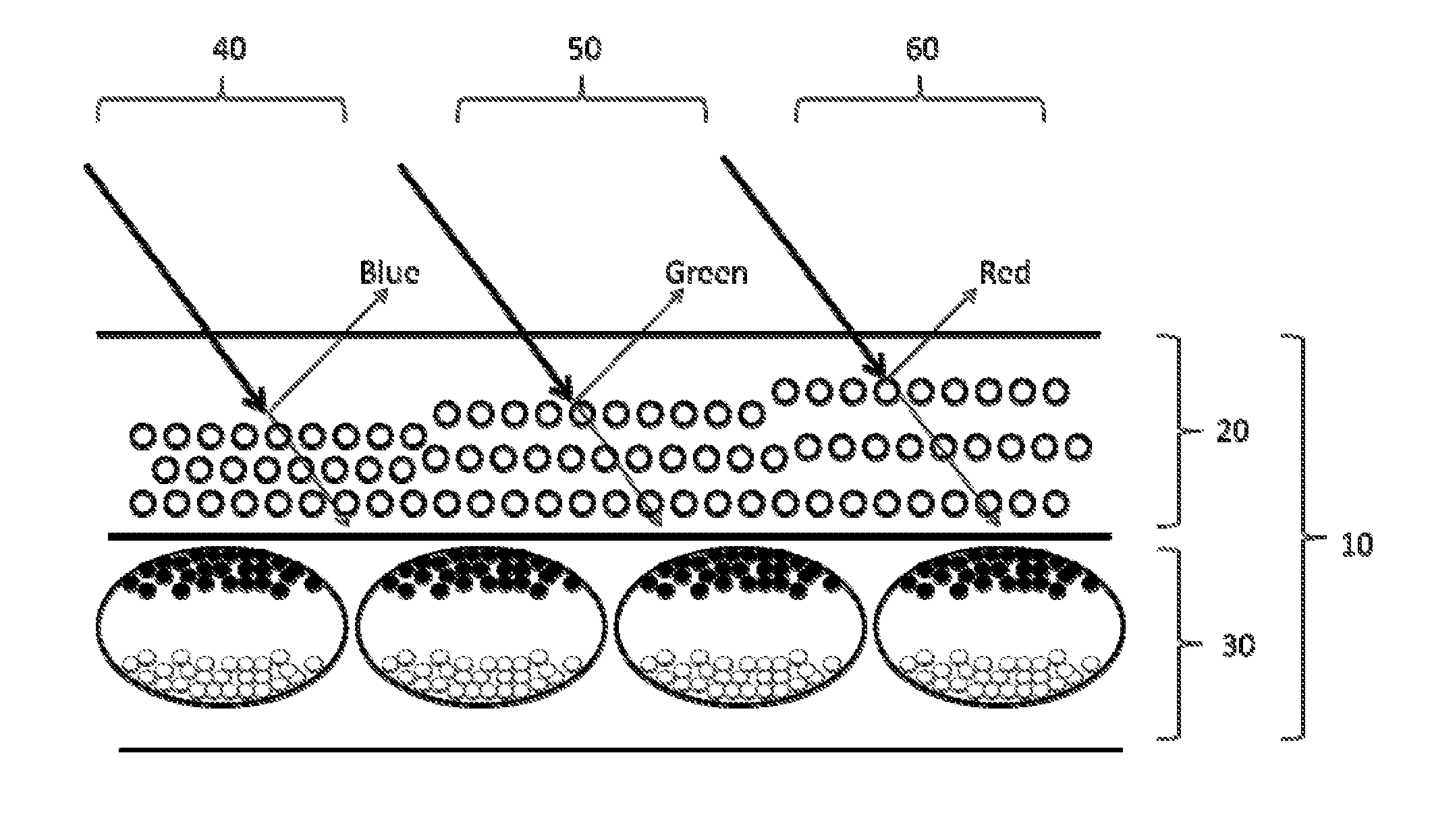
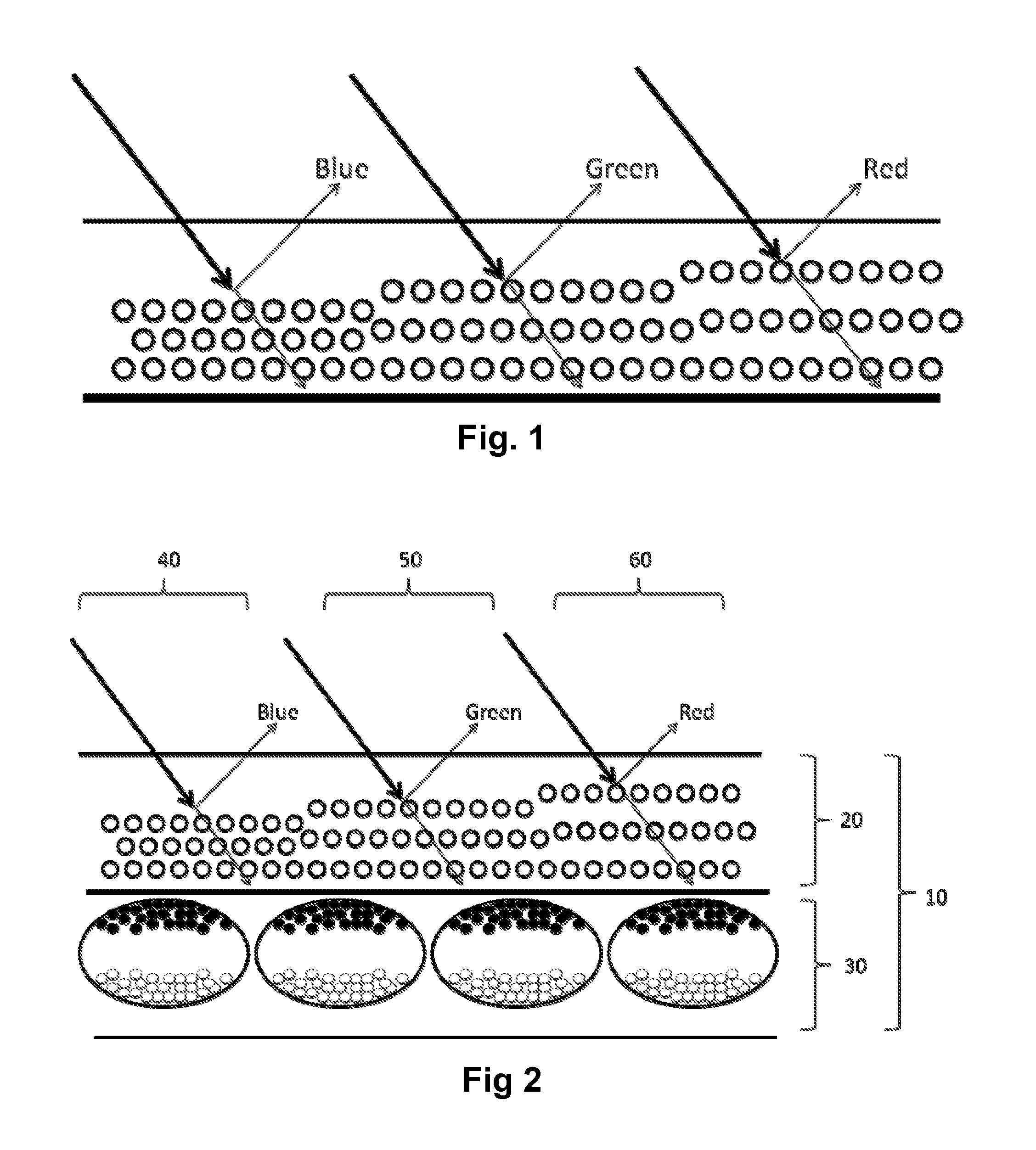
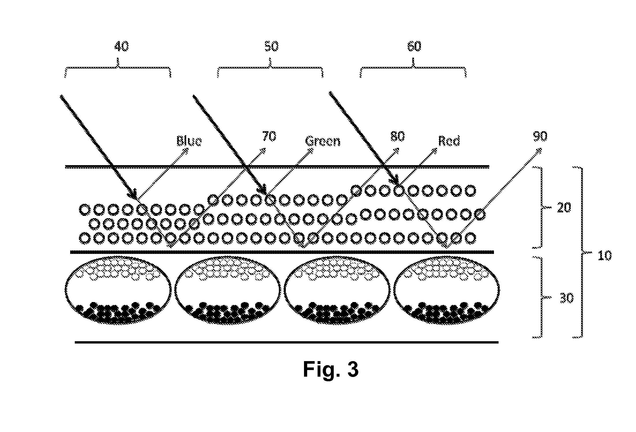
[0015]As indicated above, the present invention provides a WSR display comprising a WSR medium and, disposed adjacent the WSR medium, a backing member having a first, non-reflective optical state, and a second, reflective optical state. The backing member is switchable between its first and second optical states on a pixel-by-pixel basis, the pixels of the backing member being substantially aligned with the pixels of the WSR medium.

[0016]In principle, the backing member used in the present display can be any member have non-reflective and reflective states. For example, in very large (billboard size) displays having pixels of the order of centimeters square, the backing member may be, for example, a mechanical shutter; such a shutter could have a plurality of vanes which can be rotated between a closed position in which they lie parallel to the plane of the layer of the WSR medium and present a reflective surface towards the layer of WSR medium, and an open position, in which they l...


PUM

PropertyMeasurementUnit
reflectivityaaaaaaaaaa
electrochromicaaaaaaaaaa
electro-wettingaaaaaaaaaa

Abstract

A wavelength selective reflection display (10) comprises a wavelength selective reflection medium (20) and a backing member (30) having a first, non-reflective optical state, and a second, reflective optical state. Both the wavelength selective reflection medium (20) and the backing member (30) are divided into pixels (40, 50, 60), and the backing member (30) is switchable between its first and second optical states on a pixel-by-pixel basis. The pixels of the backing member (30) are substantially aligned with those of the wavelength selective reflection medium (20).

Description

BACKGROUND OF INVENTION[0001]This invention relates to electro-optic displays. More specifically, this invention relates to reflective displays based upon electrically-addressable, color-selective media.[0002]There have recently been developed displays that selectively reflect different colors in response to an applied electric field, and which do so not by relying on the use of conventional optical absorbers such as dyes or pigments but by exploiting optical effects such as interference and diffraction. Thus, for example, IMOD (interferometric modulator display) devices in which the spacing between a mirror and a partial reflector is controlled in response to an applied field may be constructed such that only certain wavelengths are strongly reflected, depending upon the relationship between the spacing and the wavelength of the light, as described for example in U.S. Pat. No. 5,835,255. More recently, synthetic photonic crystals have been developed whose refractive index varies pe...

Claims


Application Information

Patent Timeline
Patent Type & Authority Applications(United States)
IPC IPC(8): G02F1/167G02F1/19G02F1/16757
CPCG02F2201/343G02F1/167G02F1/16757
Inventor TELFER, STEPHEN J.PAOLINI, JR., RICHARD J.MCCREARY, MICHAEL D.COLE, DAVID JOHN
Owner E INK CORPORATION
Why Eureka
Try Eureka