Terminal, base station, response method, and retransmission control method

a response method and retransmission control technology, applied in the direction of wireless communication, transmission path sub-channel allocation, wireless commuication services, etc., can solve problems such as throughput degradation, increase the amount of interference in pucch, carrier characteristic collapse, etc., to prevent throughput degradation, without increasing the number of signaling bits

Active Publication Date: 2012-11-22
PANASONIC INTELLECTUAL PROPERTY CORP OF AMERICA
View PDF3 Cites 15 Cited by
  • Summary
  • Abstract
  • Description
  • Claims
  • Application Information

AI Technical Summary

Benefits of technology

[0014]The present invention provides a terminal, a base station, a response method and a retransmission control method capable of switc

Problems solved by technology

In such a case, when a response signal of each component band is individually transmitted in each uplink component band (Non-Bundling), there is a problem that a single-carrier characteristic collapses, that is, a problem that the amount of interference in PUCCH

Method used


Image

  • Terminal, base station, response method, and retransmission control method
  • Terminal, base station, response method, and retransmission control method
  • Terminal, base station, response method, and retransmission control method

Examples


embodiment 1

[0030][Configuration of Terminal]

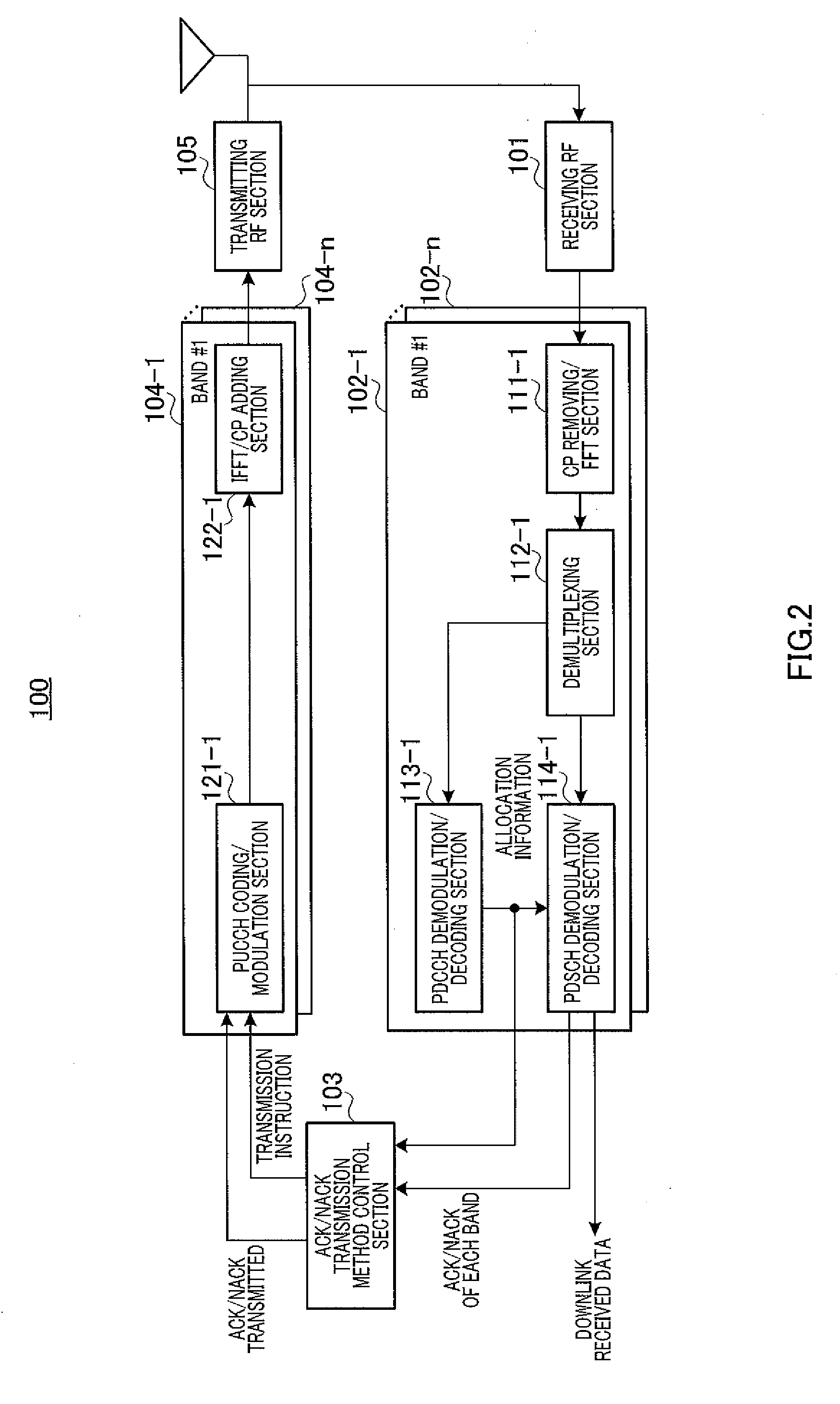
[0031]FIG. 2 is a block diagram showing a configuration of terminal 100 according to Embodiment 1 of the present invention. In FIG. 2, terminal 100 includes receiving RF section 101, reception processing sections 102-1 to n, ACK / NACK transmission method control section 103, transmission processing sections 104-1 to n and transmitting RF section 105.

[0032]Receiving RF section 101 applies radio reception processing (down-conversion, A / D conversion or the like) to a received signal received via an antenna. This radio reception processing is performed on each downlink component band. That is, receiving RF section 101 also performs processing of demultiplexing the received signal into individual downlink component bands. The received signals of the respective downlink component bands (#1 to #n) obtained in receiving RF section 101 are outputted to reception processing sections 102-1 to n corresponding to downlink component bands #1 to #n respectively.

[003...

embodiment 2

[0112]Embodiment 2 uses a degree of distribution to each downlink component band using, as criteria, total resource quantities allocated to an arbitrary terminal among a plurality of downlink component bands as a whole used for carrier aggregation as a “base station transmission parameter.”

[0113]Since basic configurations of a base station and a terminal according to Embodiment 2 are common to those in Embodiment 1, these configurations will be described using FIGS. 2 to 5.

[0114]In terminal 100 of Embodiment 2, ACK / NACK transmission method control section 103 has a function similar to that of Embodiment 1. However, as described above, Embodiment 2 is different from Embodiment 1 in that the degree of distribution to each downlink component band is used as the “base station transmission parameter.”

[0115]To be more specific, in ACK / NACK transmission method control section 103, parameter calculation section 131 calculates the “base station transmission parameter” based on resource alloc...

embodiment 3

[0132]As a “base station transmission parameter,” Embodiment uses total allocated resource quantities allocated to an arbitrary terminal with respect to a total bandwidth of a plurality of downlink component bands used for carrier aggregation, that is, an occupancy of the arbitrary terminal in all downlink component bands (group of component bands used) used in the arbitrary terminal. Thus, it is possible to prevent system throughput degradation while giving priority to a terminal carrying out large-volume communication.

[0133]The basic configurations of the base station and the terminal according to Embodiment 3 are common to those of Embodiment 1, and therefore these configurations will be described using FIGS. 2 to 5.

[0134]ACK / NACK transmission method control section 103 in terminal 100 of Embodiment 3 has a function similar to that of Embodiment 1. However, as described above, Embodiment 3 is different from Embodiment 1 in that the occupancy (that is, terminal occupancy) of termi...


PUM


Abstract

Disclosed are a terminal, a base station, a response method, and a retransmission control method, which are capable of switching the response signal transmission method while preventing throughput degradation and without increasing the number of signaling bits. A bundling determination unit (132) of a terminal (100) determines parameters that denote the allocated resource quantities that are allocated thereto from a base station (200), or in other words, a downstream band that is included in a bundling group and a downstream band that is not included in the bundling group, from among a plurality of downstream bands on the basis of base station transmission parameters. Specifically, a degree of resource share (Xn) that is allocated from each respective downstream band to the terminal (100) is employed in the base station transmission parameters.

Description

TECHNICAL FIELD[0001]The present invention relates to a terminal, a base station, a response method and a retransmission control method.BACKGROUND ART[0002]3GPP LTE-Advanced which is an evolved version of LTE is studying Carrier-Aggregation that performs transmission / reception by bundling a plurality of LTE bands to realize faster transmission (e.g., see Non-Patent Literature 1). LTE terminals detect whether or not a downlink data channel (PDSCH) signal has been received without errors and transmit a response signal thereof (ACK / NACK) to a base station using an uplink control channel (PUCCH). An ACK / NACK transmission method considered in the case of Carrier-Aggregation will be described using FIG. 1.[0003]A terminal individually receives downlink data (PDSCH) for each component band and performs error detection on each piece of data. The terminal transmits the error detection result (response signal) to the base station in an uplink component band corresponding to a downlink compone...

Claims


Application Information

Patent Timeline
IPC IPC(8): H04W72/04
CPCH04L1/16H04W28/20H04W72/0413H04L5/0055H04L1/1854H04L1/1864H04L1/1635H04W72/21
Inventor YOSHIDA, TADASHIFUKUOKA, MASARUIWAI, TAKASHINISHIO, AKIHIKONAKAO, SEIGOHOSHINO, MASAYUKIIMAMURA, DAICHI
Owner PANASONIC INTELLECTUAL PROPERTY CORP OF AMERICA
Why Eureka
Try Eureka