

Stationary chain guide
- Summary
- Abstract
- Description
- Claims
- Application Information
AI Technical Summary
Benefits of technology
Problems solved by technology
Method used
Image

Examples
first embodiment
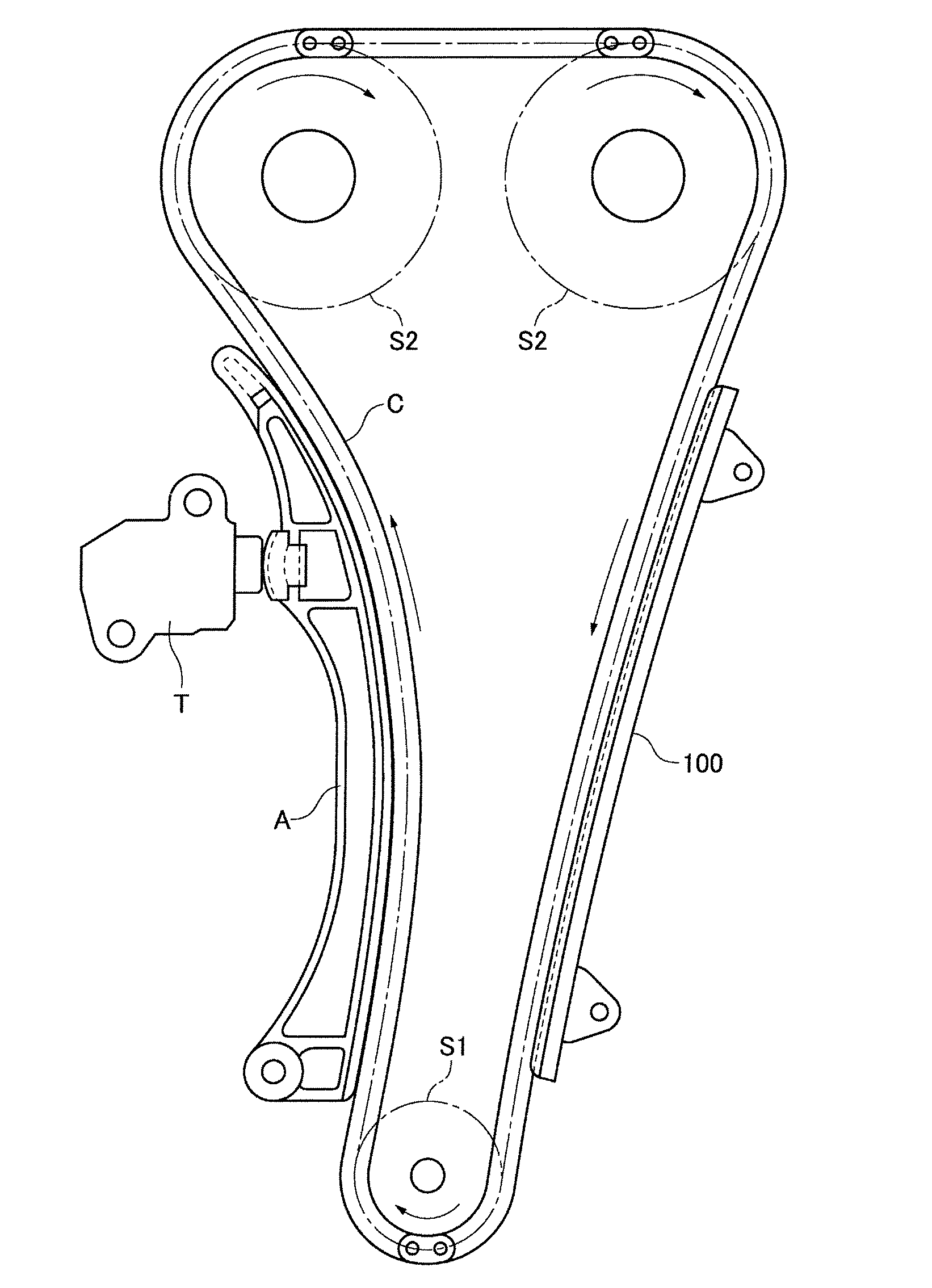
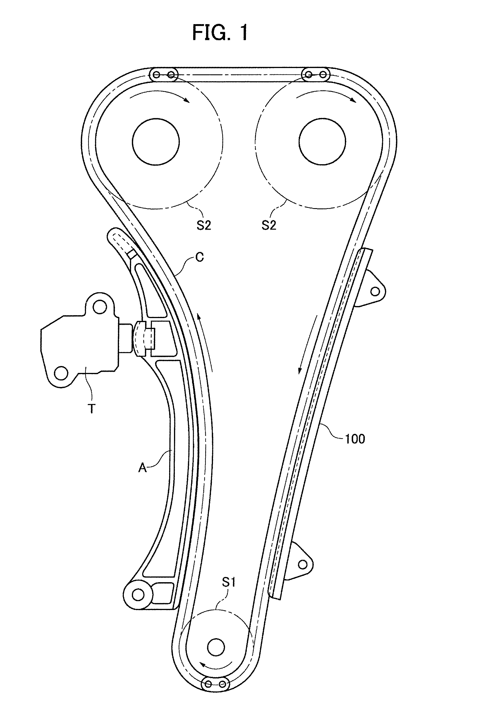
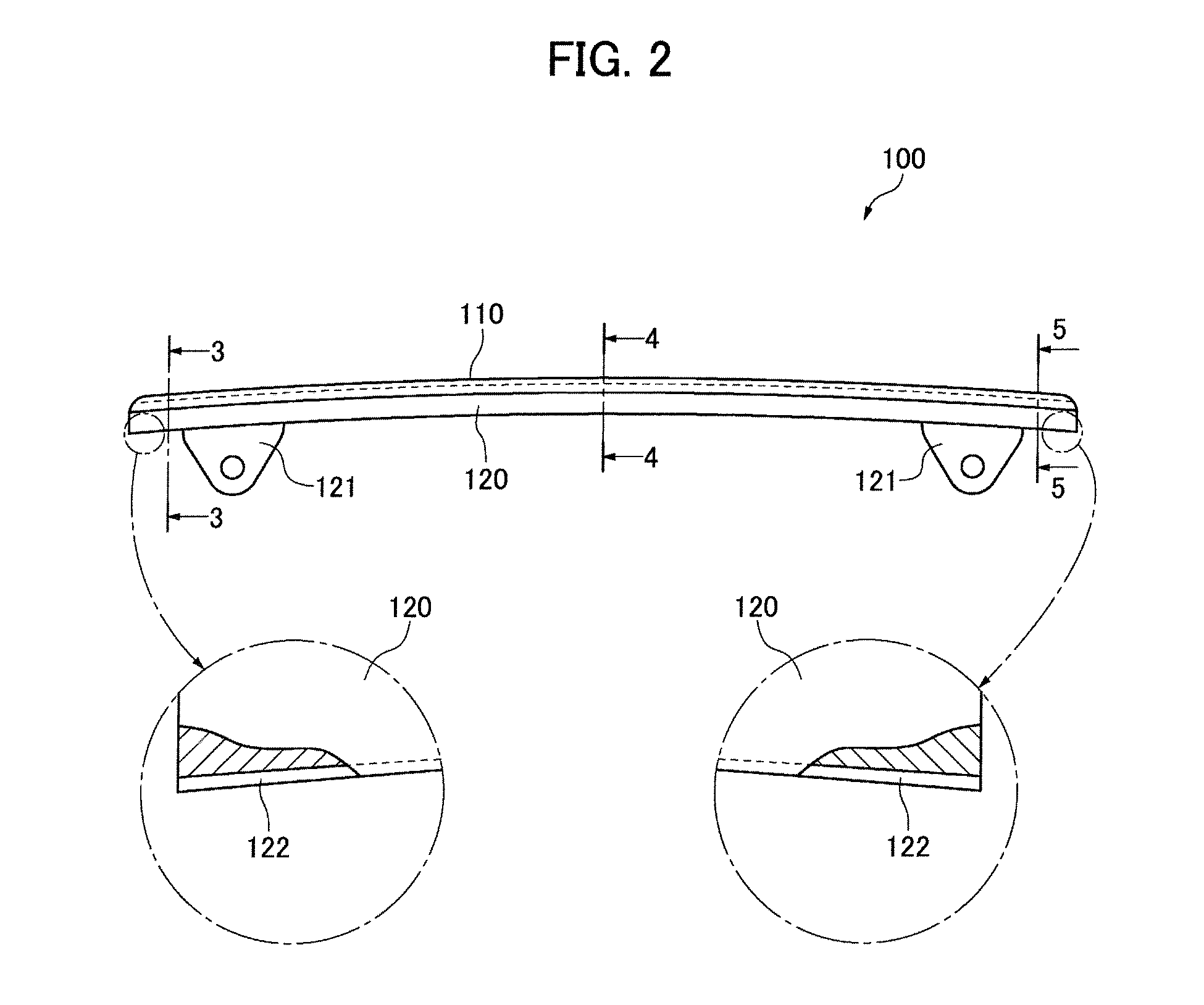
[0035]In the stationary guide, illustrated in FIGS. 2-5, an elongated stationary guide 100 includes a shoe 110 having an elongated, convexly curved, sliding contact curved surface on which the timing chain C travels along the direction of elongation of the guide. The shoe 110 is preferably composed of a nylon resin, and the base plate 120, which extends along the back of the shoe 110, and supports the shoe, can be composed of steel, although other materials such as aluminum can be used.
[0036]The guide 100 has mounting brackets 121, which are preferably unitary parts of the base plate 120. Each of these mounting brackets 121 has a through hole for receiving a mounting bolt (not shown) by which the base plate is fixed to an engine block for fixing the base plate 120 to the engine. The brackets 121 are longitudinally spaced from each other, one being and located adjacent the chain entry end of the base plate 120 at the right side of FIG. 2, and the other being located adjacent the chai...
second embodiment
[0045]In the second embodiment, the narrow reinforcing groove 222, which extends longitudinally along the back of the base plate 220, gradually becomes deeper, proceeding from the ends of the guide toward its central region. Thus, as shown in FIGS. 7 and 9, the depth Dc of the groove at the central region is greater than the depth De adjacent the ends of the guide.
[0046]As in the first embodiment, improved resistance to bending deformation of the base plate is achieved, when compared to a case in which the narrow reinforcing groove is of uniform depth along its length. However, whereas the guide of the first embodiment exhibits improved resistance to breakage due to impact, because in the second embodiment, a greater degree of work-hardening occurs in the central region of the base plate, the guide of the second embodiment exhibits improved resistance to breakage due to excessive tension in the timing chain C.
[0047]The third embodiment of an stationary guide of the invention, illust...
PUM
 Abstract
Description
Claims
Application Information