Passive exercise equipment

a technology of exercise equipment and equipment, applied in the field of passive exercise equipment, can solve the problems of affecting the health of elderly people, affecting the performance of elderly people, staggering and off-balance, etc., and achieve the effect of well-balanced stimulus

Inactive Publication Date: 2012-11-22
PANASONIC CORP
View PDF3 Cites 7 Cited by
  • Summary
  • Abstract
  • Description
  • Claims
  • Application Information

AI Technical Summary

Benefits of technology

[0028]In this configuration, a user can alternately reciprocate the user's feet every one back-and-forth motion, and receives well-balanced stimulus on the user's feet and can do a training best suited to actual walking.

Problems solved by technology

It is however difficult for aged persons whose athletic performance is decreased to walk because of incapable of performing the walking movement smoothly, which results in injury accidents caused by falling while walking.
There is also a possibility that even younger person cannot walk well after convalescing from his or her bone fracture or the like, i.e., nonambulatory condition for a prolonged period of time, because he or she has difficulties in a center-of-gravity shift required for walking, and coordinated movements of contraction and relaxation timing with respect to each muscle of joints, thereby resulting in stagger and off-balance.
However, in the passive exercise machine of the patent document 1, moving the foot supports at the same time results in user's trunk swing and center-of-gravity stagger.
A heavy burden is required of a user having a remarkable deterioration in balance capacity in particular, and it is accordingly difficult to do exercise continuously.

Method used


Image

  • Passive exercise equipment
  • Passive exercise equipment
  • Passive exercise equipment

Examples


embodiment 1

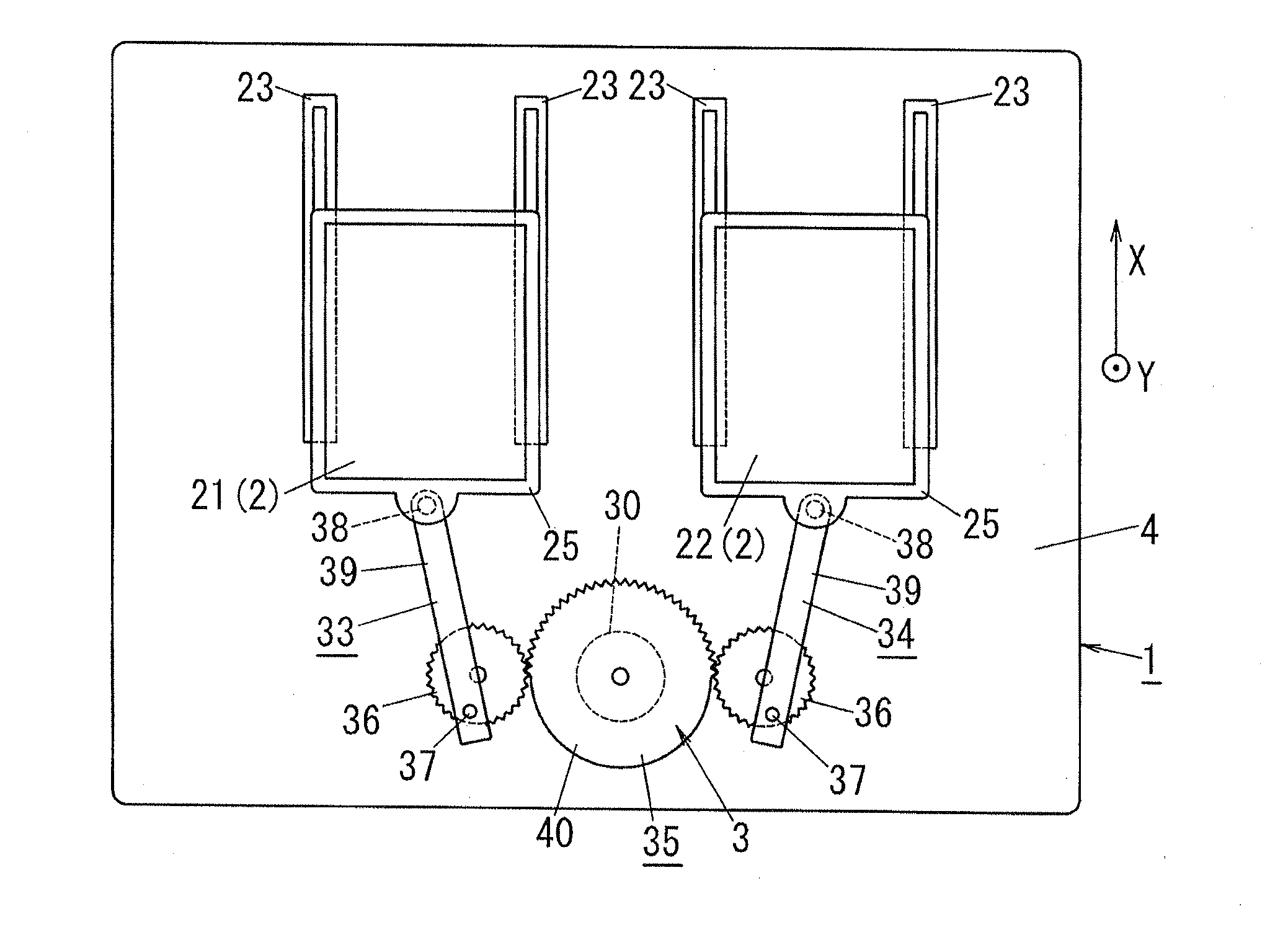
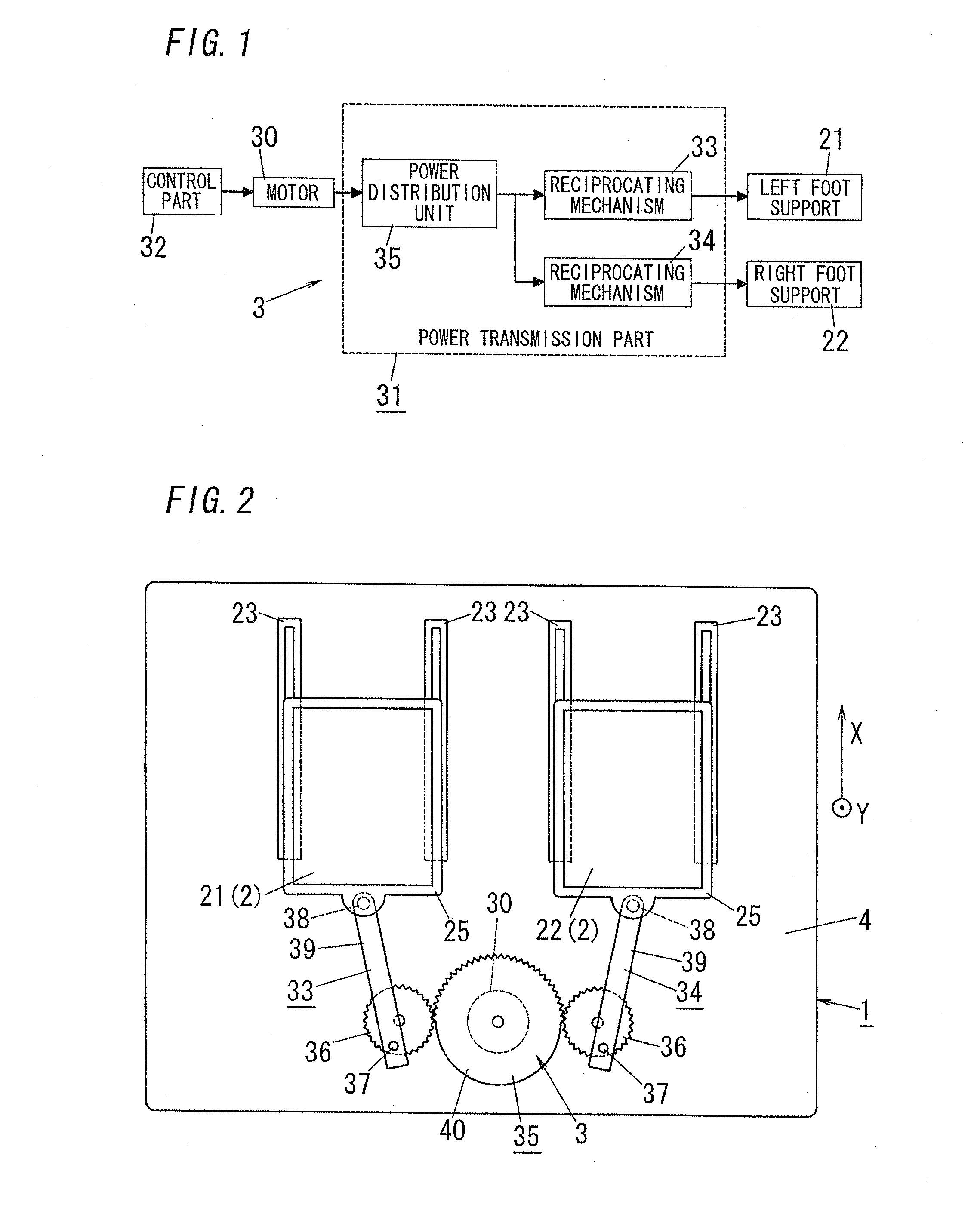
[0045]As shown in FIG. 2, a passive exercise equipment 1 of the embodiment has, on the base 4, left and right foot supports 21 and 22 on which user's left and right feet are rested, respectively, (hereinafter simply referred to as “foot supports 2” when they are not distinguished in particular) and a drive unit 3 configured to drive the foot supports 2. The base 4 is in the shape of a rectangle and forms, together with a cover (not shown), a housing in which the drive unit 3 is put.

[0046]The passive exercise equipment 1 is explained. In this embodiment, the equipment is used in a state that a user stands on the base 4 put on a floor to rest the user's left and right feet on the left and right foot supports 21 and 22, respectively (a standing position). The upper and lower sides of the passive exercise equipment 1 put on the floor are hereinafter referred to as an up-and-down direction, and an array direction of the left and right foot supports 21 and 22 are referred to as a lateral ...

embodiment 2

[0069]A passive exercise equipment 1 of the embodiment differs from the passive exercise equipment 1 of the embodiment 1 in that a second foot support 2, as a pivoting foot side, restrained at a reference position in a horizontal plane is dorsiflexed. A posture of the second foot support 2 of which upper face is horizontal is hereinafter referred to as a basic posture. A posture of the second foot support 2 that user's toe side is turned upward from the basic posture is hereinafter referred to as a dorsiflexion posture.

[0070]In the embodiment, as shown in FIG. 7, the drive unit 3 has a first turning mechanism for left foot 51 configured to dorsiflex the left foot support 21 by motive energy distributed through the power distribution unit 35, and a first turning mechanism for right foot 52 configured to dorsiflex the right foot support 22.

[0071]Each foot support 2 is swingably supported by a corresponding frame 25. Specifically, as shown in FIG. 8, the two foot supports 2 have two pi...

embodiment 3

[0089]A passive exercise equipment 1 of the embodiment differs from the passive exercise equipment 1 of the embodiment 2 in that the first foot support 2, at a side of a foot other than a pivoting foot of a user, reciprocated in a front-back direction in a horizontal plane is plantarflexed. A posture of the foot support 2 of which upper face is horizontal is hereinafter referred to as a basic posture. A posture of the foot support 2 that a user's toe side is turned downward from the basic posture is hereinafter referred to as a plantarflexion posture.

[0090]In the embodiment, the drive unit 3 has a second turning mechanism for left foot configured to plantarflex the left foot support by motive energy distributed through the power distribution unit, and a second turning mechanism for right foot configured to plantarflex the right foot support by motive energy distributed through the power distribution unit. The second turning mechanisms are provided in place of the first turning mecha...


PUM


Abstract

A drive device has a motor for generating a drive force, a power transmission unit for transmitting the force generated by the motor to first and second foot support tables, thereby moving the foot support tables, and a control unit for controlling the motor. The power transmission unit is connected to an output shaft of the motor. The power transmission unit has a left foot reciprocation mechanism for reciprocating a left foot support table, a right foot reciprocation mechanism for reciprocating a right foot support table, and a power divergence unit for diverging the force of the motor into the reciprocation mechanisms and transmitting the force thereto. The power transmission unit alternately transmits the rotation force of the motor to the left and right foot support tables, thereby causing the left and right foot support tables to alternately move in a forward and backward direction in increments of one reciprocation.

Description

TECHNICAL FIELD[0001]The invention relates to a passive exercise equipment configured to regularly move foot supports on which user's feet are rested, thereby providing the user with a passive exercise.BACKGROUND ART[0002]Walking movement requires persons to each put their own weight on their own pivoting feet while at the same time moving their own feet other than their own pivoting feet forward.[0003]It is however difficult for aged persons whose athletic performance is decreased to walk because of incapable of performing the walking movement smoothly, which results in injury accidents caused by falling while walking.[0004]There is also a possibility that even younger person cannot walk well after convalescing from his or her bone fracture or the like, i.e., nonambulatory condition for a prolonged period of time, because he or she has difficulties in a center-of-gravity shift required for walking, and coordinated movements of contraction and relaxation timing with respect to each ...

Claims


Application Information

Patent Timeline
Patent Type & Authority Applications(United States)
IPC IPC(8): A61H1/02
CPCA61H1/005A61H1/0266A61H1/0262A61H2201/164A61H2201/1669A61H2201/1215
Inventor OCHI, KAZUHIROGOTO, TAKAOSHINOMIYA, YOUICHIOZAWA, TAKAHISA
Owner PANASONIC CORP
Why Eureka
Try Eureka