Fluid Transfer Device having Modular Connection

Inactive Publication Date: 2012-11-29
BOGNER JAMES
View PDF11 Cites 10 Cited by
  • Summary
  • Abstract
  • Description
  • Claims
  • Application Information

AI Technical Summary

Benefits of technology

[0020]A further object of the present invention is to provide a fluid transfer channel that is adapted to accommodate larger containers and allow transfer of both liquid and air between containers, preventing air pockets or vacuums from bl

Problems solved by technology

Consolidation of such liquid products may be burdensome, and in some cases impossible.
This results in wasted product and increased costs for a restaurant/establishment owner or homeowner, who must purchase more of the product or containers thereof than would otherwise be necessary if the entire product was otherwise capitalized on.
Unitary structures and devices of this type generally do not accommodate large discrepancies between container sizes or openings thereof.
They are not adapted to provide the modularity required to connect a first and second container of different dimension and create an efficient pathway therebetween.
The device is constructed using a single molding operation such as injecti

Method used


Image

  • Fluid Transfer Device having Modular Connection
  • Fluid Transfer Device having Modular Connection
  • Fluid Transfer Device having Modular Connection

Examples


first embodiment

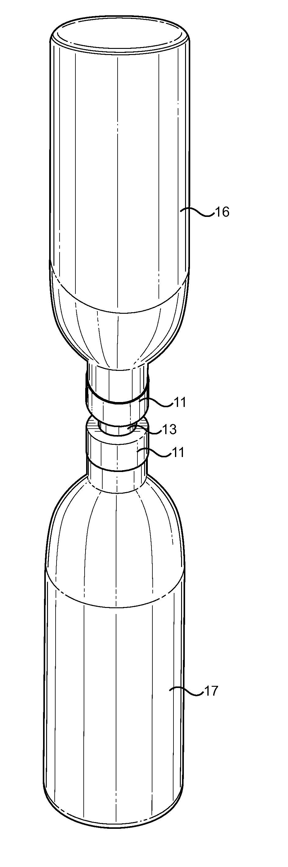
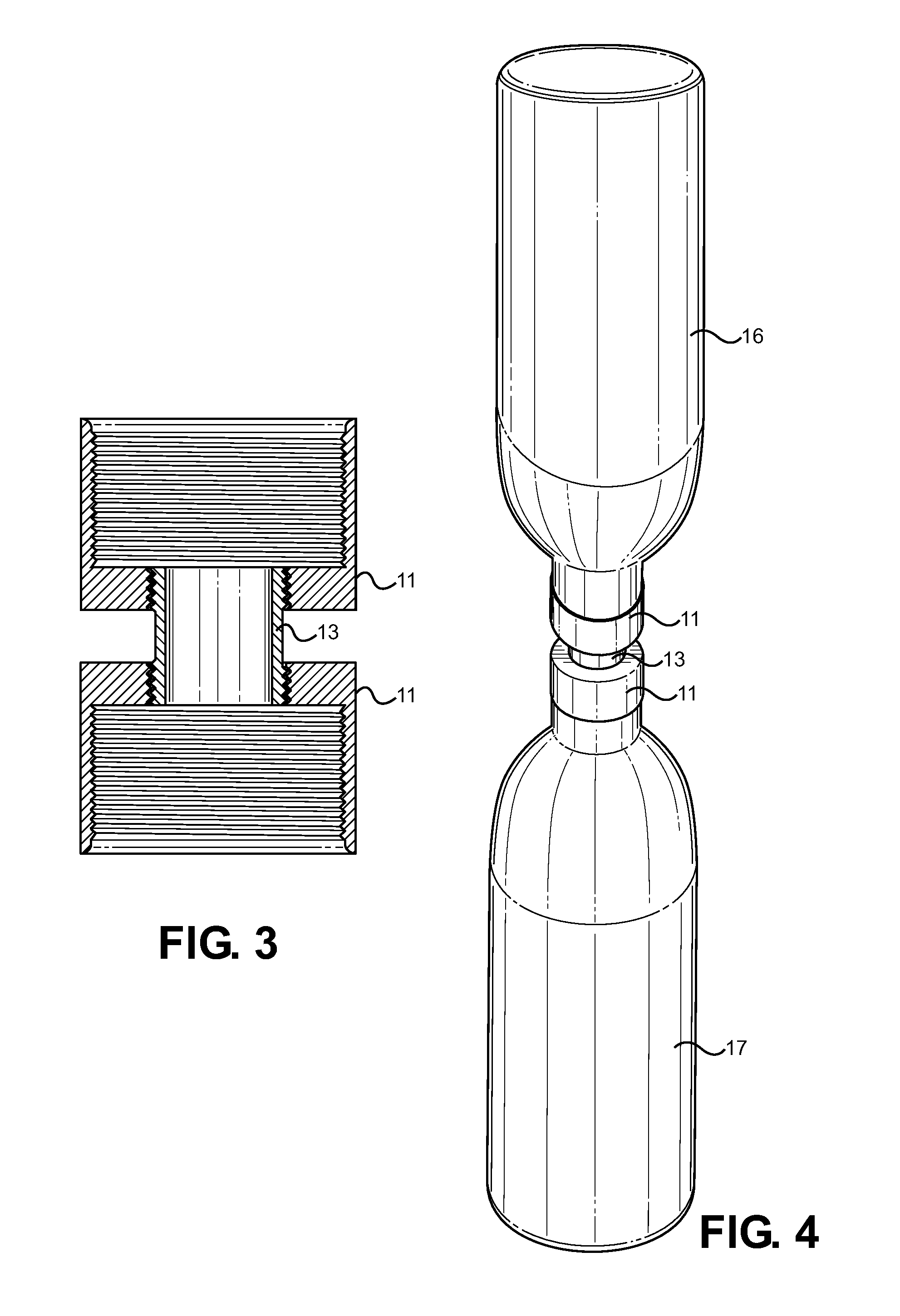
[0033]Referring now to FIG. 3, there is shown a cross section view of the present invention, wherein the first and second caps 11 are connected via the central fluid transfer channel 13 to create a pathway for fluid between joined containers. In an exemplary embodiment, both caps 11 provide a first opening that employs a threaded connection to their respective containers, while providing a second opening having a threaded connection adapted to join the caps together via the threaded connection of the central channel 13. The threaded connections ensure an air tight and secure connection, whereafter the elements may be disengaged from the containers and separated into individual components for cleaning and storage. The separatabliity of the elements further allows different sized caps 11 to be mated, providing for connection of dissimilar containers.

second embodiment

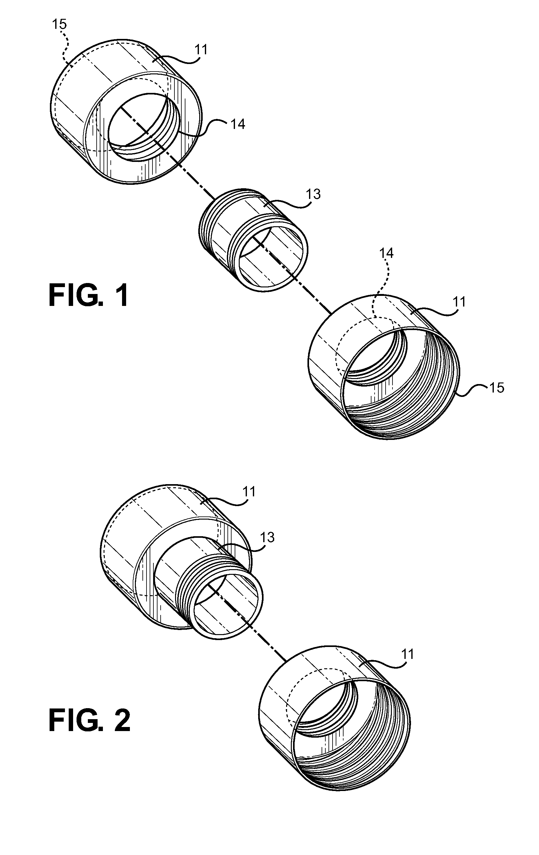
[0034]the present invention provides a cap having an integrated channel in place of its second opening. This provides two distinct styles of caps: a first style wherein a channel is provided, and a second style wherein an opening is provided adapted to connect to a channel. This configuration reduces part count and reduces the steps for setting up and utilizing the device. Further, the first style cap having the integrated channel may stay connected to a larger container of condiment fluid, wherein this larger container is utilized to refill and dispense fluid to smaller, more individualized containers for use by consumers.

[0035]Within the channel of either embodiment of the present invention may be provided a valve that controls the flow of fluid and air from the attached container. This valve is controlled from the exterior of the channel and allows a user to attach the channel (or cap having an integrated channel) to a container desired to be emptied. When the valve is in a close...


PUM


Abstract

A universal fluid transfer device is disclosed for transferring fluid from a first container to another utilizing gravity feed. The device comprises a first and second container-connecting cap adapted to securely connect to a receiving and emptying container opening, respectively. The caps preferably threadably engage each container opening, while a central transfer channel threadably connects to each cap to effectuate a path for fluid transfer therebetween. A plurality of cap sizes can be utilized in conjunction with the fluid transfer channel to accommodate various container opening sizes, providing transfer of fluid between identical or dissimilar container openings using a single device that can modularly adapt to different dimensions.

Description

CROSS REFERENCE TO RELATED APPLICATION[0001]This application claims the benefit of U.S. Provisional Application No. 61 / 490,263 filed on May 26, 2011, entitled “Gravity Cap.”BACKGROUND OF THE INVENTION[0002]1. Field of the Invention[0003]The present invention relates to gravity fed fluid transfer devices for communicating fluid from one container to another. More specifically, the present invention pertains to a fluid transfer device that comprises container opening attachment caps that are adapted to securely mount to a receiving and emptying container using independent caps, wherein the caps then connect together via a central channel to transfer liquid and air from one container to the other. Each cap can be sized to fit an intended container opening and operate with a differently sized second cap that attaches to a second container.[0004]Transferring liquid from one container or vessel to another is a common problem in the restaurant and food industry as well as in the home, wher...

Claims


Application Information

Patent Timeline
IPC IPC(8): B65D51/00
CPCB65D71/502
Inventor BOGNER, JAMES
Owner BOGNER JAMES
Why Eureka
Try Eureka