Pushing device

a technology of pushing device and push rod, which is applied in the direction of tractors, ways, fittings, etc., can solve the problems of delayed drive of the pushing vehicle, serious installation mistakes, and inability of the hgv driver to release, and achieve the effect of simple mounting

Active Publication Date: 2012-11-29
JOSEPH VOEGELE AG
View PDF25 Cites 7 Cited by
  • Summary
  • Abstract
  • Description
  • Claims
  • Application Information

AI Technical Summary

Benefits of technology

[0023]In light of the above problems in practical application and the known state of the art, the object of the present invention is, using simple technical design features, to create an improved pushing

Problems solved by technology

In this situation, however, it frequently happens that serious installation mistakes are made because the HGV driver applies the brakes of the HGV for too long and/or with too much force.
This can lead to a delayed drive of the pushing vehicle, as a result of which installation errors occur in the pavement.
On the other hand, the HGV driver is not permitted to release the brake of the HGV completely, because otherwise the HGV would be pushed away towards the front due to the effect of the momentum of the material sliding out.
There is a risk, however, that the HGV collides against the pushing device too quickly, or that the HGV driver drives against the pushing device for too long, which can lead to a displacement of the paver and in this way to unwanted line-shaped imprints in the roadway surface.
Pushing devices with coil springs, however, have the disa

Method used


Image

  • Pushing device
  • Pushing device
  • Pushing device

Examples


Embodiment Construction

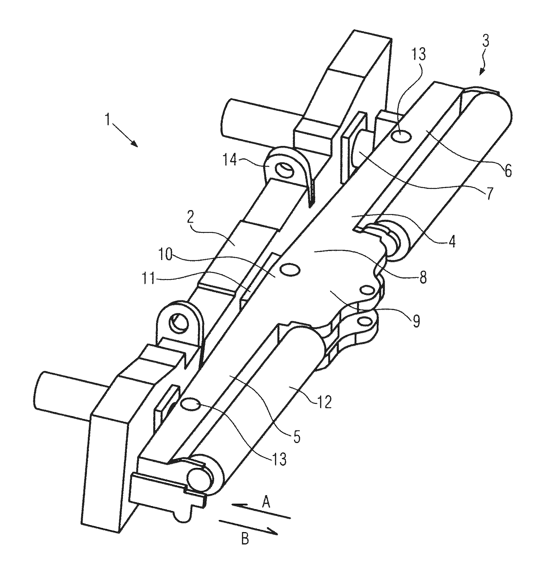
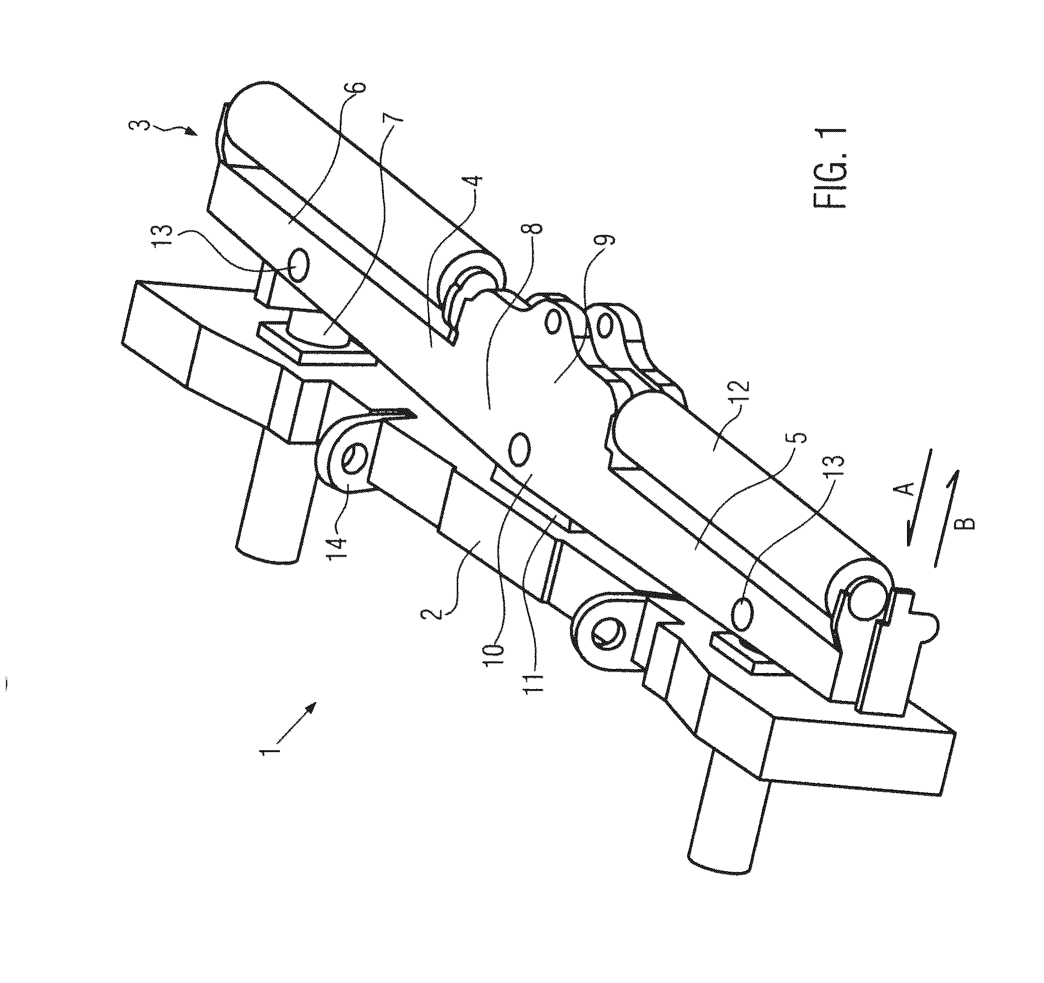
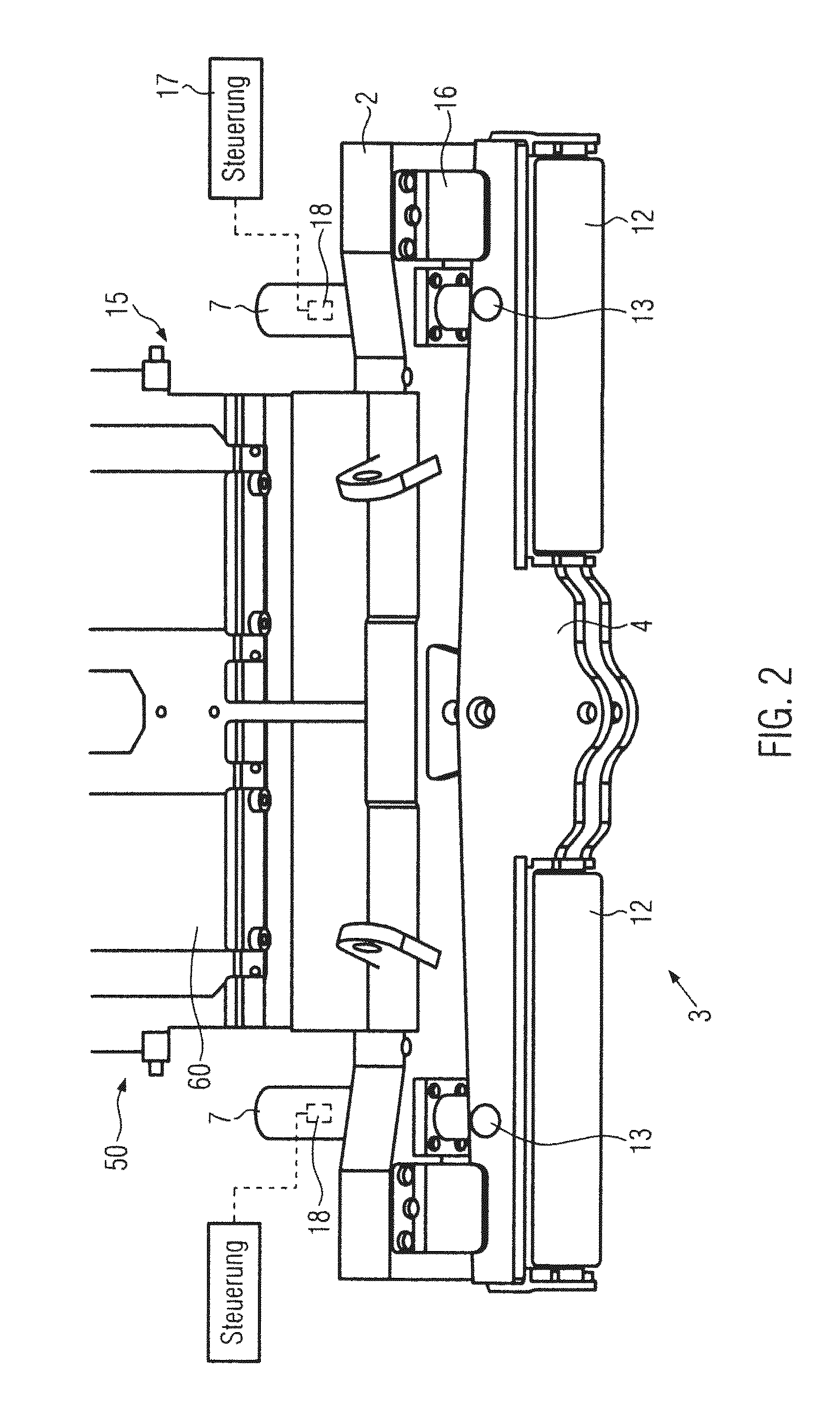
[0050]FIG. 1 shows a pushing device 1 that can be attached to a road paver or feeder vehicle 50 (see FIG. 2). The pushing device 1 comprises a pushing unit 3 that is arranged on a cross-arm 2 in accordance with FIG. 1 and that is formed as a pushing bar 4. The pushing bar 4 is mounted to a spring-absorber unit 7 on a first outer section 5 and on a second outer section 6. The spring-absorber unit 7 provides a movable connection between the pushing bar and the cross-arm 2, whereby the pushing unit 3 can be displaced in a first direction A against the spring rate of the spring-absorber unit 7 onto the cross-arm 2, but also can be pushed away from the cross-arm 2 in a second direction B by the spring-absorber unit 7. Even although it is not shown in FIG. 1, it is also possible for a plurality of spring-absorber units 7 to be arranged next to one another at equal distances or in sets along the pushing bar 4 in order to attach the pushing unit 3 to the cross-arm 2 in a movable manner.

[005...


PUM


Abstract

A pushing device that can be attached to a road paver or feeder vehicle. The pushing device is attachable to a chassis component of the road paver or the feeder vehicle and comprises a pushing unit that is attached in a movable manner to the chassis component by means of at least a spring-absorber unit. The pushing unit can be displaced relative to the chassis component in a first direction and a second direction, whereby the spring-absorber unit has a greater spring rate during a movement of the pushing unit in the first direction than in the second direction.

Description

BACKGROUND OF THE INVENTION[0001]The present invention relates to a pushing device and to a vehicle for receiving installation or paving material, particularly a road paver or feeder vehicle[0002]During the installation of pavements, a heavy goods vehicle (HGV) loads road pavers or feeders with the material that is to be installed. The material is thereby tipped by the HGV directly into the hopper of the road paver or of the feeder.[0003]To transfer the material, a loaded HGV slowly drives backwards to the vehicle that is to be loaded, stops a short distance away from the vehicle and waits until the approaching paver or feeder is docked to the chassis of the HGV by means of a pushing device. In most cases, the pushing device docks to the rear tires of the HGV. After the docking process, the road paver or feeder accelerates the HGV from a standing position to the installation speed and pushes said HGV in front of itself until such a time as the HGV has been fully unloaded.[0004]The d...

Claims


Application Information

Patent Timeline
IPC IPC(8): B60D3/00
CPCE01C2301/08E01C19/48
Inventor BUSCHMANN, MARTINSCHMIDT, THOMASWEISER, RALF
Owner JOSEPH VOEGELE AG
Why Eureka
Try Eureka