Spark plug and method of manufacturing spark plug

a technology of spark plugs and spark plugs, which is applied in the manufacture of spark plugs, combustion processes, lighting and heating apparatus, etc., can solve the problems of structurally difficult gap g correction (gap adjustment)

Active Publication Date: 2012-11-29
NGK SPARK PLUG CO LTD
View PDF0 Cites 41 Cited by
  • Summary
  • Abstract
  • Description
  • Claims
  • Application Information

AI Technical Summary

Benefits of technology

[0042]In the ignition plug of the present invention, one end of a rod-shaped ground electrode is fixed to the metallic shell such that the ground electrode is cantilevered and extends in a chord direction of the ignition chamber. Therefore, a load in a radial direction of the ignition chamber can be applied to the ground electrode at any position between the fixed end of the ground electrode and the other end. Therefore, even in the case of a prechamber plug in which the center electrode and the ground electrode are provided within the ignition chamber, the gap can be readily adjusted. For example, the gap is greatly adjusted by applying a load to a portion of the ground electrode near the fixed end, or the gap is finely adjusted by applying a load to the free end side of the ground electrode.
[0060]Since the radius difference λ1 between the inner diameter of the metal fitting and the outer diameter of the convex portion of the welding jig and the radius difference λ2 between the inner diameter of the metallic shell and the diameter of a portion of the welding jig facing the inner circumferential surface of the metallic shell are determined to satisfy the relation λ2>λ1, it becomes possible to more reliably prevent the welding jig from contacting the metallic shell.

Problems solved by technology

However, in the prechamber plug, since the center electrode 103 and the ground electrodes 108 are located within the ignition chamber 105, correction of the gap G (gap adjustment) is structurally difficult to perform.

Method used


Image

  • Spark plug and method of manufacturing spark plug
  • Spark plug and method of manufacturing spark plug
  • Spark plug and method of manufacturing spark plug

Examples


first embodiment

[0120]A first embodiment of the present invention will now be described with reference to drawings.

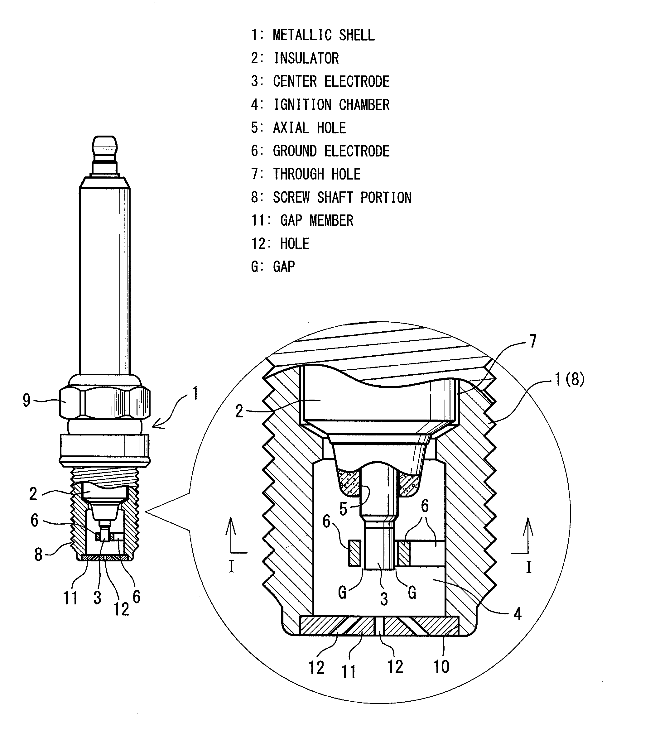
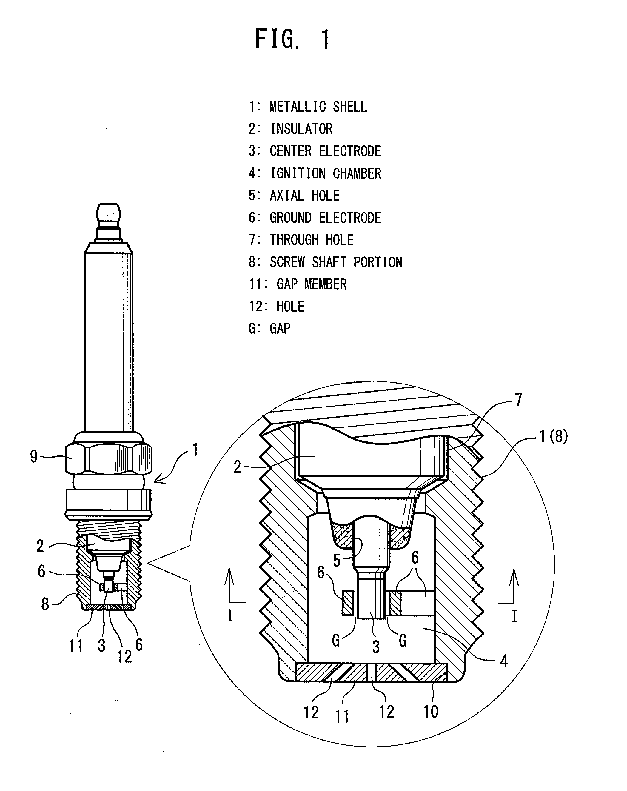
[0121]As shown in FIG. 1, an ignition plug of the first embodiment includes a metallic shell 1; an insulator 2 attached to the metallic shell 1; a center electrode 3 attached to the insulator 2; an ignition chamber 4 formed at a front end portion of the metallic shell 1 (on the side where the center electrode 3 is disposed); and ground electrodes 6 disposed in the ignition chamber 4 and facing the circumferential surface of the center electrode 3 directly or indirectly.

[0122]The metallic shell 1 is a tubular member which has a through hole 7 extending therethrough in the axial direction thereof, and is formed of, for example, low carbon steel. The metallic shell 1 has, at its front end with respect to the axial direction, a screw shaft portion 8, which is screwed into a plug attachment hole (not shown) of a cylinder head or the like. Also, the metallic shell 1 has, at its rear end, a t...

second embodiment

[0155]Next, a second embodiment of the present invention will be described with reference to FIGS. 16 to 44. Notably, an object of the second embodiment of the present invention is to provide an ignition plug in which separate ground electrodes are joined to a metallic shell and which is improved in the joint strength and durability of the ground electrodes, and a manufacturing method which enables manufacture of such an ignition plug.

[0156]Basic Structure of the Second Embodiment

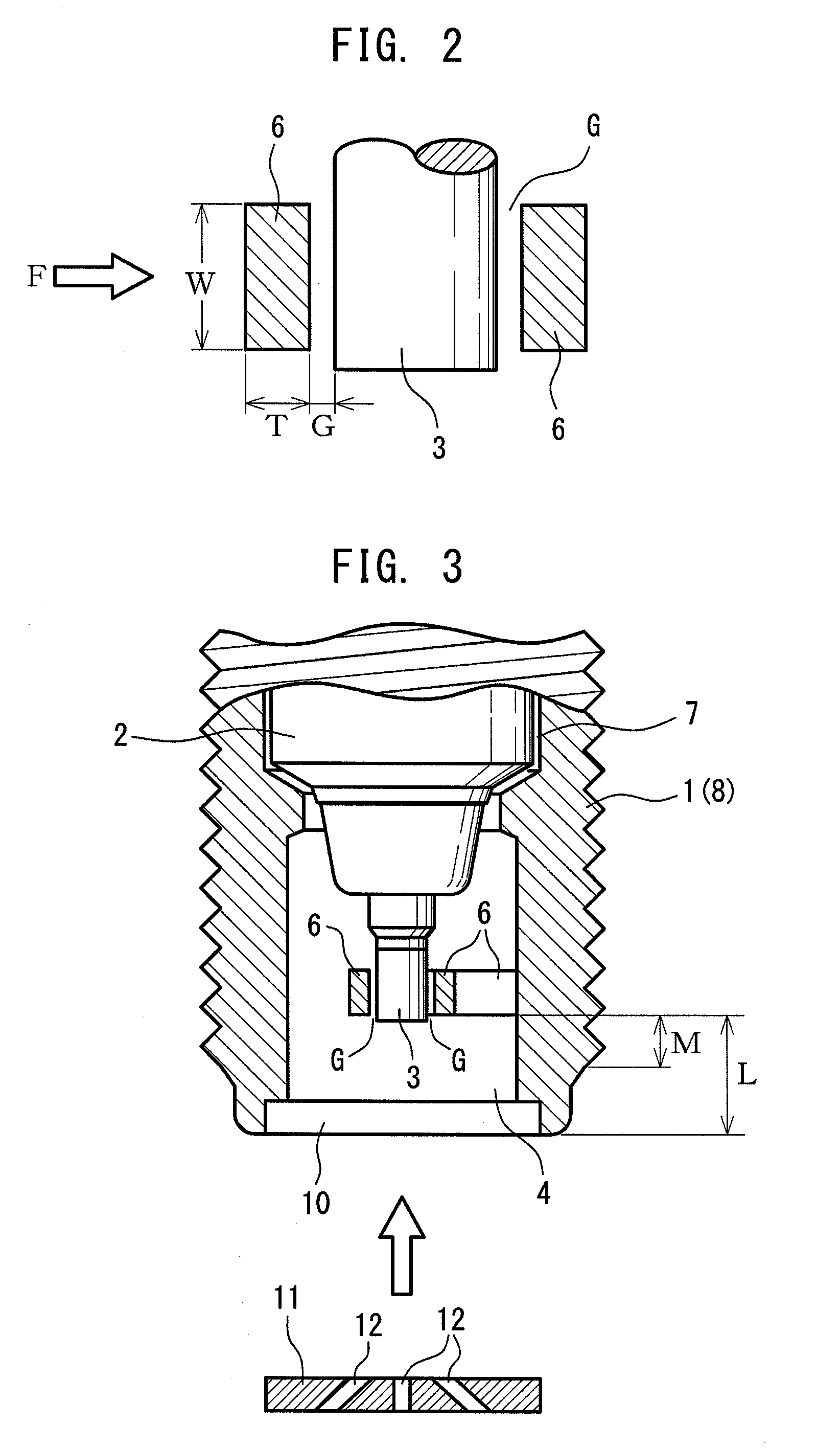
[0157]As shown in FIG. 16, the ignition plug of the second embodiment includes a metallic shell 1; an insulator 2 attached to the metallic shell 1; a center electrode 3 attached to the insulator 2; ground electrodes 6 whose proximal end portions 6a are disposed at a front end portion of the metallic shell 1 (on the side where the center electrode 3 is disposed) and whose distal end portions face the circumferential surface of the center electrode 3 directly or indirectly with gaps G formed therebetween; and...

third embodiment

[0250]In the gap adjustment steps of the above-described first and second embodiments, when a rod-shaped tool 50 is inserted into the front end opening 10 of the metallic shell 1 so as to apply a load on one ground electrode 6 as shown in FIG. 55, the rod-shaped tool 50 is obliquely inserted to press the ground electrode 6 in a lever fashion. Therefore, so as to follow the inclination of the tool 50, the ground electrode 6 may tilt at an angle θ in relation to the circumferential surface of the center electrode 3. As a result, a gap difference may arise between the front end side (the upper corner portion in FIG. 55) and the rear end side (the lower corner portion in FIG. 55) of the single ground electrode 6. In view of such a drawback, a gap adjustment step which enables the gap adjustment to be performed more accurately will now be described as a third embodiment.

[0251]Gap Adjustment Step

[0252]In the gap adjustment step of the third embodiment, the gaps (clearances) G1 to G4 betwe...


PUM


Abstract

An ignition plug having a metallic shell with a through hole extending therethrough in an axial direction, an insulator fitted into the through hole of the metallic shell and having an axial hole extending in the axial direction, and a center electrode fitted into the axial hole of the insulator. The ignition plug further includes a cap member which covers a front end opening of the metallic shell, provided on a front end side thereof where the center electrode is disposed, to thereby form an ignition chamber at the front end portion of the metallic shell, and a ground electrode disposed within the ignition chamber and facing a circumferential surface of the center electrode directly or indirectly.

Description

FIELD OF THE INVENTION[0001]The present invention relates to an ignition plug and a method of manufacturing the ignition plug.BACKGROUND OF THE INVENTION[0002]Int'l Publication No. WO 2006 / 011950 discloses a conventional ignition plug. As shown in FIGS. 14 and 15 of the present application, a conventional ignition plug includes an electrically conductive metallic shell 101 having a through hole 100 extending therethrough in the axial direction. An insulator 102 is attached to the through hole 100 of the metallic shell 101, and a center electrode 103 attached to the insulator 102. Defining the side where the center electrode 103 is disposed as a “front end side,” the metallic shell 101 has an opening (front end opening) 104 on the front end side. The ignition plug includes a cap member 107 having a hole 106. Cap member 107 is provided at the front end of the metallic shell 101 and covers the front end opening 104 of the metallic shell 101, to thereby form an ignition chamber 105. Fou...

Claims


Application Information

Patent Timeline
Patent Type & Authority Applications(United States)
IPC IPC(8): H01T13/20H01T21/06
CPCH01T13/32H01T21/02H01T13/54H01T13/467
Inventor SAKAKURA, YASUSHIMATSUNAGA, YUICHI
Owner NGK SPARK PLUG CO LTD
Why Eureka
Try Eureka