
Symmetric differential inductor structure

a technology of differential inductance and structure, applied in the field of symmetric differential inductor structure, can solve the problems of not being able to achieve a fully symmetric structure, adversely affect the product yield, and reduce the product profit, so as to increase the product profit and yield

Active Publication Date: 2012-11-29
SILICONWARE PRECISION IND CO LTD
View PDF0 Cites 1 Cited by
  • Summary
  • Abstract
  • Description
  • Claims
  • Application Information

AI Technical Summary

Benefits of technology

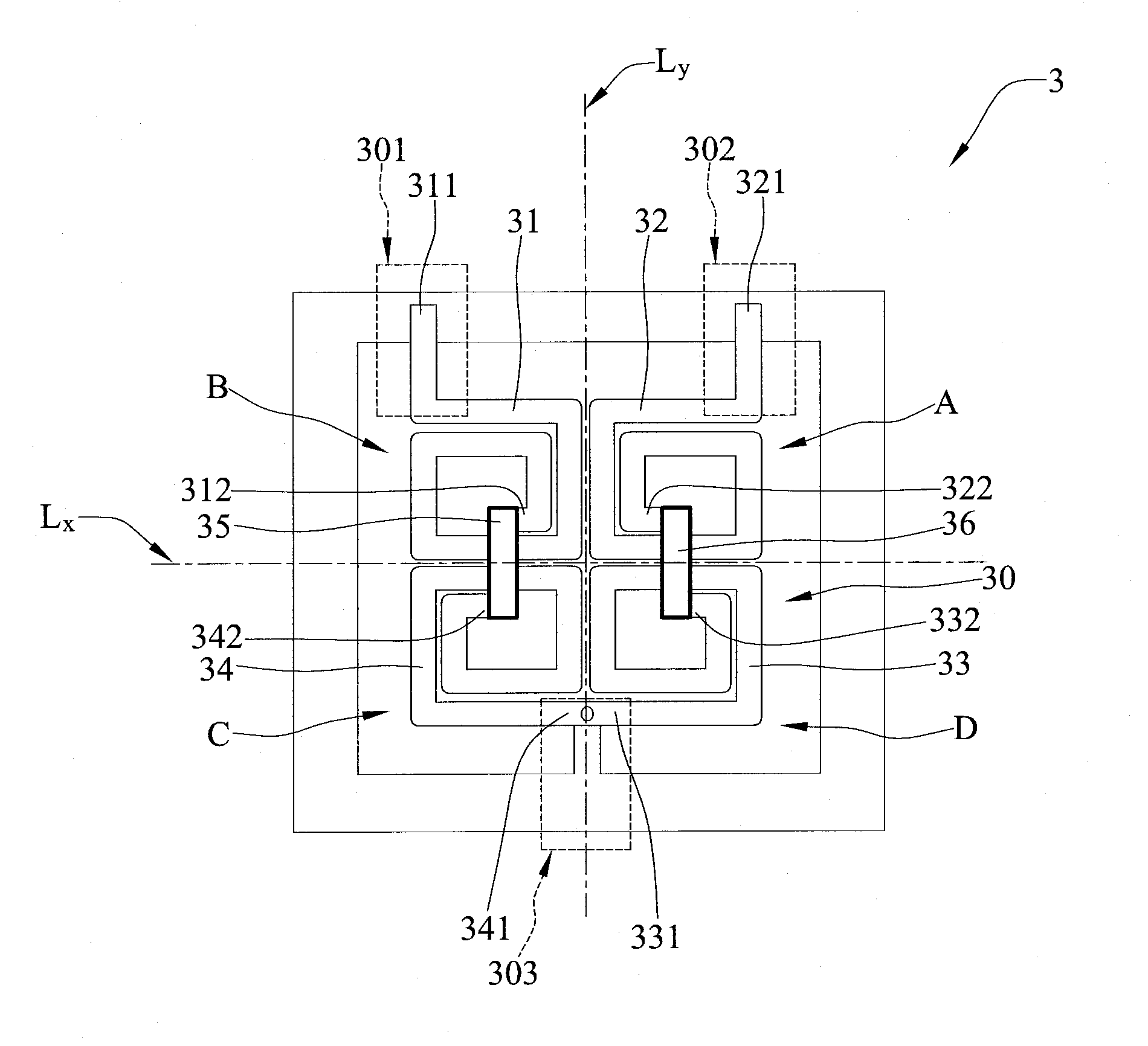
The present invention provides a symmetrical differential inductor structure on a substrate. This structure includes four spiral conductive wirings and one conductive wiring over the first and fourth spiral conductive wirings. The first and second spiral conductive wirings are not intersected with each other, and the third and fourth spiral conductive wirings are not intersected with each other. This results in full geometrical symmetry, which avoids the use of central conductive wirings that occupy a large area of the substrate. This increases product profit and yield.

Problems solved by technology

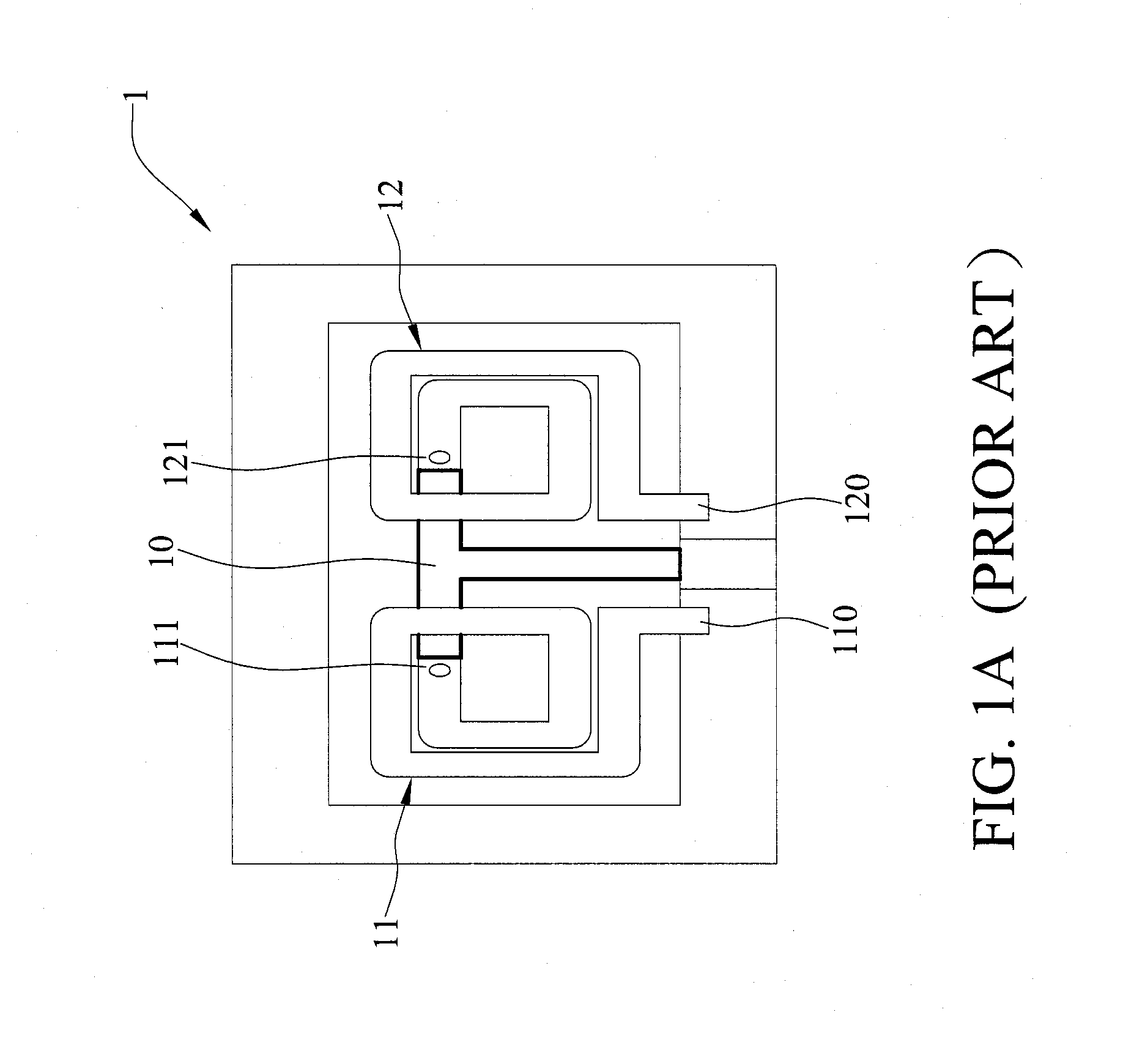
However, the T-shaped central conductive wiring 10 of the symmetric differential inductor 1 and the central conductive wiring 20 of the center-tap differential inductor 2 occupy a large area of the substrate, thereby decreasing the product profit.
Further, it is not possible to attain a fully symmetric structure due to the intersections of the spiral conductive wirings in the center-tap differential inductor 2.
As such, phase differences or other interference could occur and adversely affect the product yield and even seriously affect the inductance values and quality factors of the inductor.

Method used


Image

  • Symmetric differential inductor structure
  • Symmetric differential inductor structure
  • Symmetric differential inductor structure

Examples


Embodiment Construction

[0017]The following illustrative embodiments are provided to illustrate the disclosure of the present invention and its advantages, these and other advantages and effects being apparent to those in the art after reading this specification.

[0018]FIG. 3A shows a symmetric differential inductor structure according to the present invention. Referring to FIG. 3A, the symmetric differential inductor 3 is disposed on a substrate 30 and has a first spiral conductive wiring 31, a second spiral conductive wiring 32, a third spiral conductive wiring 33, a fourth spiral conductive wiring 34, a fifth conductive wiring 35 and a sixth conductive wiring 36.

[0019]The substrate 30 is divided into a first quadrant A, a second quadrant B, a third quadrant C and a fourth quadrant D by centerlines Lx, Ly. The substrate 30 further has a first input port 301 disposed in the second quadrant B, a second input port 302 disposed in the first quadrant region A and a third input port 303 disposed outside the fir...


PUM

PropertyMeasurementUnit
conductiveaaaaaaaaaa
areaaaaaaaaaaa
inductanceaaaaaaaaaa

Abstract

A symmetric differential inductor structure includes first, second, third and fourth spiral conductive wirings disposed in four quadrants of a substrate, respectively. Further, a fifth conductive wiring connects the first and fourth spiral conductive wirings, and a sixth conductive wiring connects the second and third spiral conductive wirings. The first and second spiral conductive wirings are symmetric but not intersected with one another, and the third and fourth spiral conductive wirings are symmetric but not intersected with one another. Therefore, the invention attains full geometric symmetry to avoid using conductive wirings that occupy a large area of the substrate as in the prior art and to thereby increase the product profit and yield.

Description

BACKGROUND OF THE INVENTION[0001]1. Field of the Invention[0002]The present invention relates to inductor structures, and, more particularly, to a symmetric differential inductor structure.[0003]2. Description of Related Art[0004]In the field of semiconductor fabrication processes, differential inductors are important passive components. Generally, there are two types of differential inductors: symmetric differential inductors and center-tap differential inductors.[0005]FIG. 1A shows a symmetric differential inductor 1. Referring to FIG. 1A, the symmetric differential inductor 1 has a T-shaped central conductive wiring 10 disposed in the center of a substrate, a first conductive wiring 11 extending from the left side of the central conductive wiring 10 in a counterclockwise spiral (moving outwards from the center), and a second conductive wiring 12 extending from the right side of the central conductive wiring 10 in a clockwise spiral. One end of the first conductive wiring 11 has a...

Claims


Application Information

Patent Timeline
Patent Type & Authority Applications(United States)
IPC IPC(8): H01F27/29
CPCH01L23/5227H01F19/04H01L2924/0002H01L2924/00
Inventor TSAI, MING-FANCHEN, KUAN-YUFANG, BO-SHIANGLEE, HSIN-HUNG
Owner SILICONWARE PRECISION IND CO LTD
Learn More