Aerial Photograph Image Pickup Method And Aerial Photograph Image Pickup Apparatus

Active Publication Date: 2012-11-29
KK TOPCON
View PDF20 Cites 32 Cited by
  • Summary
  • Abstract
  • Description
  • Claims
  • Application Information

AI Technical Summary

Benefits of technology

[0010]According to the present invention, in the aerial photograph image pickup method, comprising a step of making a flying object, which comprises a GPS device and an image pickup device for taking an image downward, fly meanderingly, a step of taking the image at each vertex where a direction is changed in the meandering flight, a step of extracting feature points from a common overlap portion of the images taken from at least three vertexes adjacent to each other, a step of determining two images of two vertexes in the images as one set and acquiring positional information of the two vertexes by the GPS device for each set regarding at least two sets, a step of performing photogrammetry of the measuring points corresponding to the feature points based on the positional information and based on the feature points of the two images and a step of determining the feature points when the surveying results of the measuring points coincide with each other in at least the two sets as tie points for image combination. As a result, it is possible to correct a tilting of the images caused due to rolling or pitching of the flying object that cannot be corrected in an image taken in the linear flight.
[0011]Further, according to the present invention, in the aerial photograph image pickup method, based on the tie points and the three-dimensional coordinates of the three vertexes measured by the GPS device, a local processing of a calculation of photographing positions of the images taken at the three vertexes and an orientation calculation of tilting are carried out. As a result, the processing can be rapidly executed, and an accurate altitude o

Problems solved by technology

In case of performing the photography by a small flying object, although it is desired for a body to be horizontal, the body actually has a light weight, and the body is often swept away by the wind, or the body is often tilted.
Therefore, in a fixedly mounted image pickup device, an optical axis is tilted depending on a state of the body, and a t

Method used


Image

  • Aerial Photograph Image Pickup Method And Aerial Photograph Image Pickup Apparatus
  • Aerial Photograph Image Pickup Method And Aerial Photograph Image Pickup Apparatus
  • Aerial Photograph Image Pickup Method And Aerial Photograph Image Pickup Apparatus

Examples


Example

[0019]By referring to the attached drawings, description will be given below on an embodiment of the present invention.

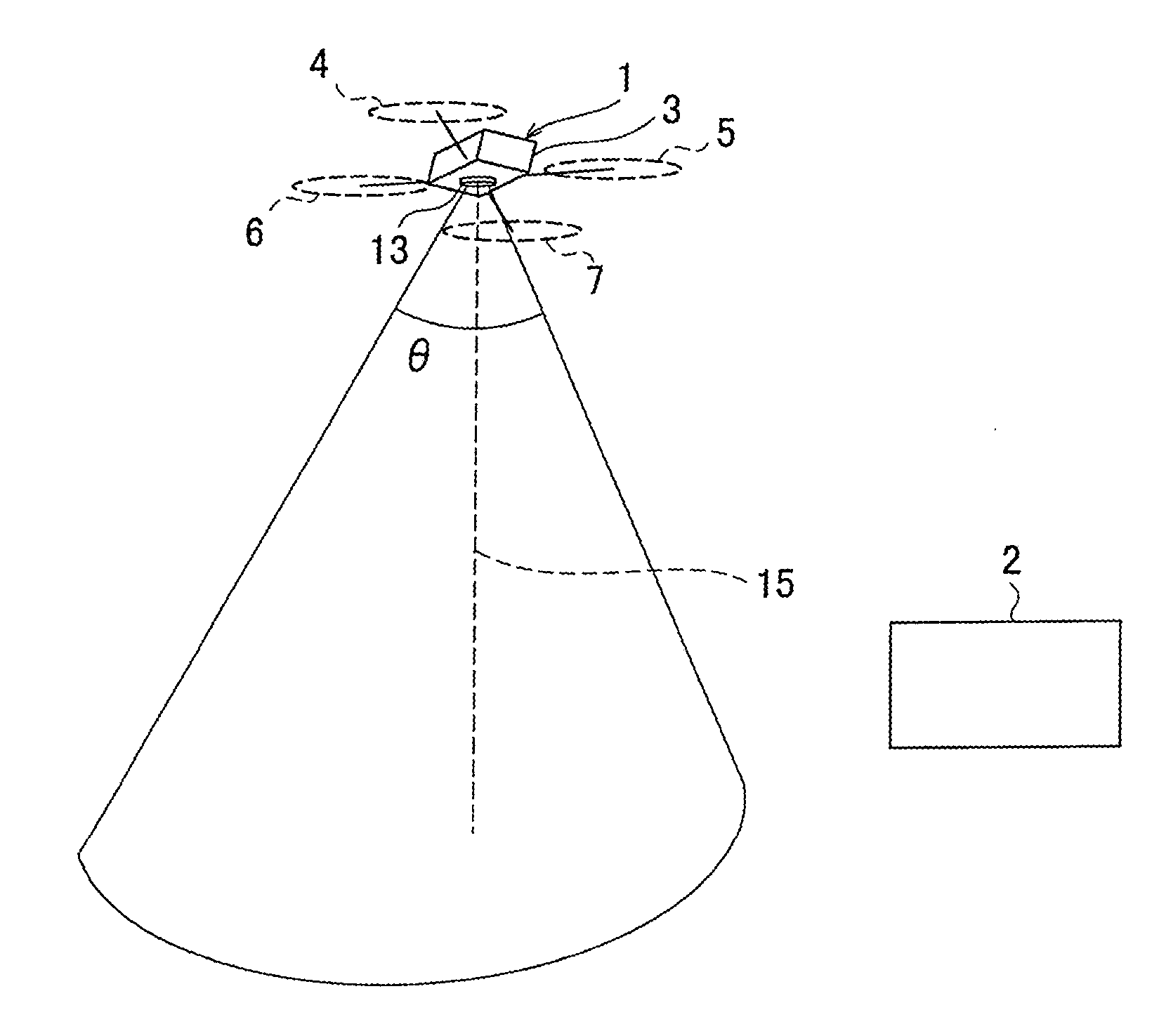
[0020]First, in FIG. 1, description will be given on a flight control system of a flying object in which the present invention is applied to.

[0021]In FIG. 1, the reference numeral 1 represents a flying object which can make an autonomous flight, the reference numeral 2 represents a base control device installed on the ground. The base control device 2 can perform the data communication with the flying object 1 and controls a flight of the flying object 1, sets or changes a flight plan and stores or manages the information collected by the flying object 1.

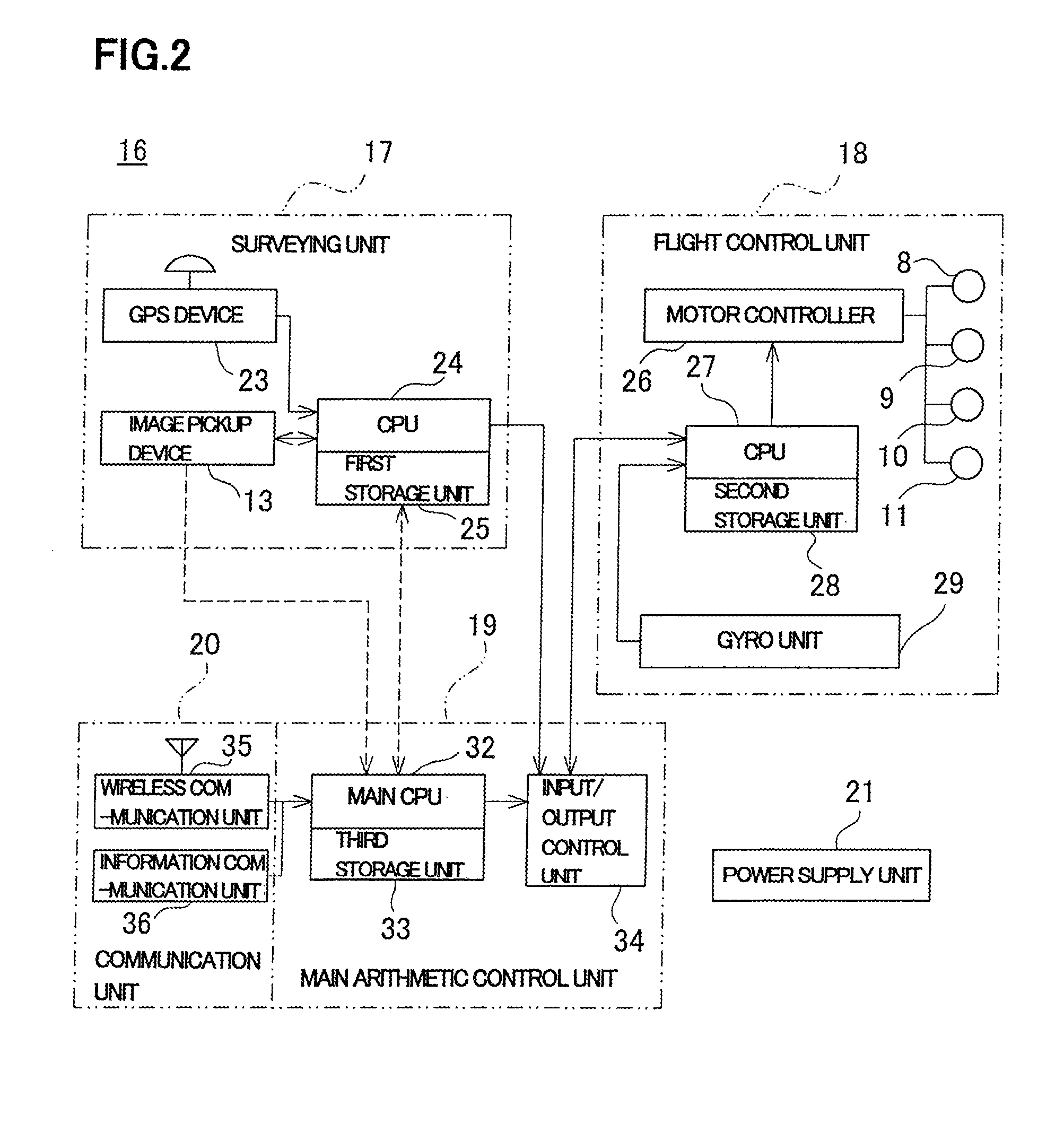
[0022]The flying object 1 is, e.g., a helicopter as a small flying object for making an autonomous flight. The helicopter 1 is flown by the remote control from the base control device 2, or the flight plan is set in a control device 16 (as described later) of the helicopter 1 from the base control device 2, and an a...


PUM


Abstract

An aerial photographing image pickup method comprises a step of making a flying object fly meanderingly, a step of taking the image at each vertex where a direction is changed in the meandering flight, a step of extracting feature points from a common overlay portion of the images taken from at least three adjacent vertices, a step of determining two images of two vertices in the images as one set and acquiring positional information of the two vertices by a GPS device for each set regarding at least two sets, a step of performing photogrammetry of the measuring points corresponding to the feature points based on positional information and based on the feature points of the two images and a step of determining the feature points when the surveying results of the measuring points coincide with each other in at least the two sets as tie points for image combination.

Description

BACKGROUND OF THE INVENTION[0001]The present invention relates to an aerial photograph image pickup method and an aerial photograph image pickup apparatus by a small Unmanned Aerial Vehicles (UAV).[0002]In the photography from the air above or the surveying from the air above, the information which cannot be acquired by the photography from the ground or the surveying on the ground can be acquired, and the photography is possible in an off-limits area, or the information in an area where the surveying is difficult can be acquired. Further, in recent years, because of the improvement in performance of a small flying object as remote controlled such as a tiny plane or a small-scale helicopter, or the like, the improvement in a remote control technology, and further, the improvement in performance of an image pickup device, the promotion of the miniaturization, and others, the image pickup device can be mounted in a small flying object. By remotely controlling the flying object, the ph...

Claims


Application Information

Patent Timeline
IPC IPC(8): H04N7/18
CPCG01C11/02G05D1/0094G03B37/02G03B35/02G03B15/006
Inventor OHTOMO, FUMIOOSARAGI, KAZUKIANAI, TETSUJIOTANI, HITOSHI
Owner KK TOPCON
Why Eureka
Try Eureka