Optical body, method of manufacturing the same, window member, fitting, and solar shading device
a technology of optical body and solar panel, which is applied in the field of optical body, can solve problems such as glare or reflection, and achieve the effect of suppressing glare and reflection
Inactive Publication Date: 2012-11-29
DEXERIALS CORP
View PDF15 Cites 40 Cited by
- Summary
- Abstract
- Description
- Claims
- Application Information
AI Technical Summary
Benefits of technology
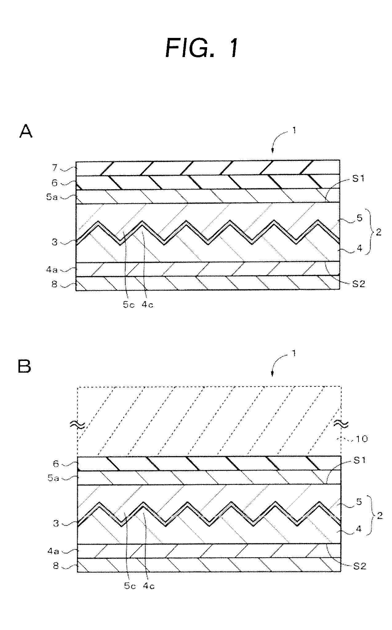
The present invention provides an optical body that can block sunlight and reduce glare and reflection. The optical body includes a first optical layer with a concave-convex surface, a transflective layer formed on the concave-convex surface, and a second optical layer formed to enclose the concave and convex portions on the concave-convex surface. The transflective layer directionally reflects a portion of light incident on the incidence surface at an incidence angle. The optical body can be used in a window member, a fitting, and a solar shading device. The technical effect of the invention is to provide an optical body that can block sunlight and reduce glare and reflection.
Problems solved by technology
Therefore, a problem of glare or reflection arises.
Method used
View moreImage
Smart ImageViewing Examples
Examples
first embodiment (
1. First embodiment (example in which structures are one-dimensionally arrayed)
second embodiment (
2. Second embodiment (example in which structures are two-dimensionally arrayed)
third embodiment (
3. Third embodiment (example of a louver-type transflective layer)
Login to View More PUM
 Abstract
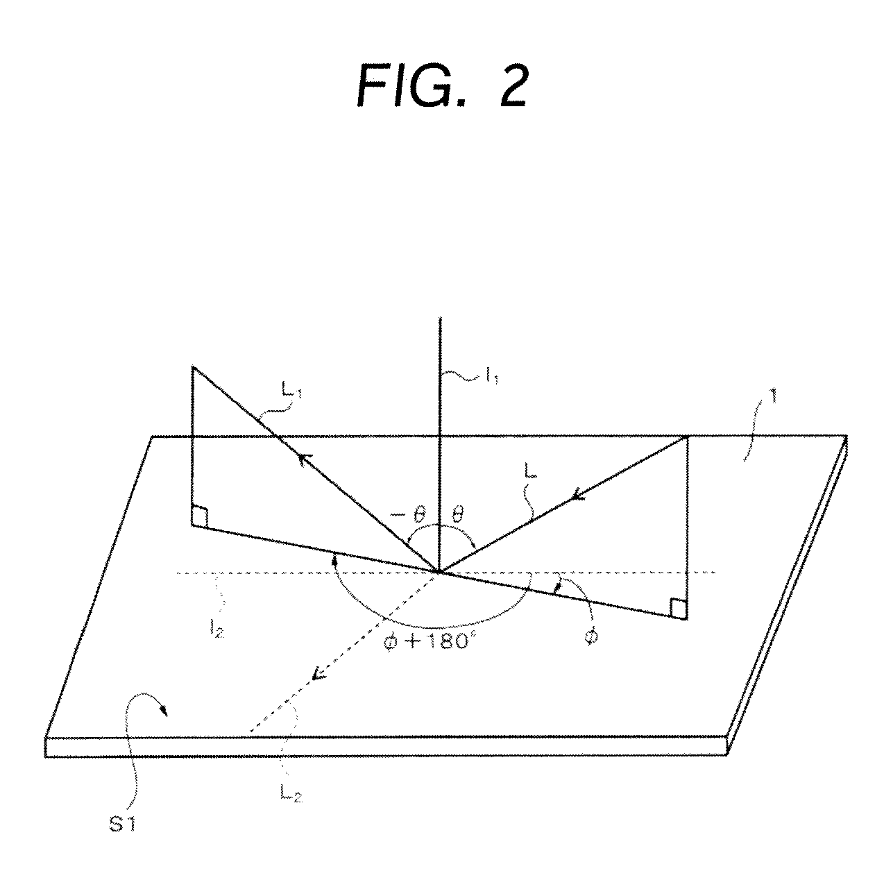
Provided is an optical body which is capable of blocking sunlight including visible light as well as suppressing glare and reflection. An optical body includes a transflective layer formed on a concave-convex surface and a second optical layer formed to enclose concave portions and convex portions on the concave-convex surface on which the transflective layer is formed. The transflective layer directionally reflects a portion of light, incident on an incidence surface at an incidence angle (θ, φ), in a direction other than a direction of regular reflection (−θ, φ+180°).
Description
TECHNICAL FIELD[0001]The present invention relates to an optical body, a method of manufacturing the same, a window member, a fitting, and a solar shading device. In particular, the invention relates to an optical body that can block sunlight.BACKGROUND ART[0002]Recently, a film or a pane for a window to block sunlight is used from the viewpoint of reducing air conditioning load. Especially, a film or a pane that blocks visible light rays as well as infrared light at the same time is used because over the half of solar energy is visible light rays. Moreover, it is important to partially block the visible light rays in view of the purpose of reducing glare caused by late afternoon sunlight.[0003]A transflective layer made of a metal obtained through film deposition is known as such a film or a pane (for example, see Patent Documents 1 to 3). However, since a transflective layer is deposited on a flat plate in these films or panes, visible light rays are reflected therefrom, thereby f...
Claims
Login to View More Application Information
Patent Timeline
 Patent Type & Authority Applications(United States)
IPC IPC(8): G02B27/00B05D5/06
CPCB32B3/30B32B7/02B32B2307/412B32B2307/416B32B2307/71B32B2419/00B32B2551/00E06B2009/2417G02B1/10G02B5/045G02B5/08G02B5/22E06B9/386G02B1/118G02B5/208
Inventor NAGAHAMA, TSUTOMUSUZUKI, MASAKITAKENAKA, HIROYAENOMOTO, MASASHI
Owner DEXERIALS CORP
Features
- R&D
- Intellectual Property
- Life Sciences
- Materials
- Tech Scout
- Unparalleled Data Quality
- Higher Quality Content
- 60% Fewer Hallucinations
Learn More Browse by: Latest US Patents, China's latest patents, Technical Efficacy Thesaurus, Application Domain, Technology Topic, Popular Technical Reports.
© 2025 PatSnap. All rights reserved.Legal|Privacy policy|Modern Slavery Act Transparency Statement|Sitemap|About US| Contact US: help@patsnap.com


