Barrier unit
a barrier unit and unit technology, applied in the field of barriers, can solve the problems of affecting the operation of the barrier unit, the failure of the opening and closing of the blades, and the possibility so as to suppress the occurrence of flare and ghosting caused by reflection of light, and facilitate conta
- Summary
- Abstract
- Description
- Claims
- Application Information
AI Technical Summary
Benefits of technology
Problems solved by technology
Method used
Image
Examples
first embodiment
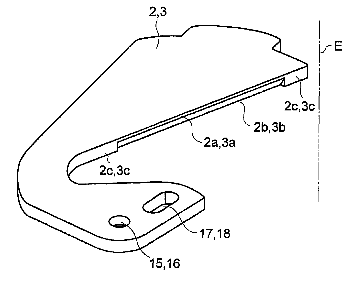
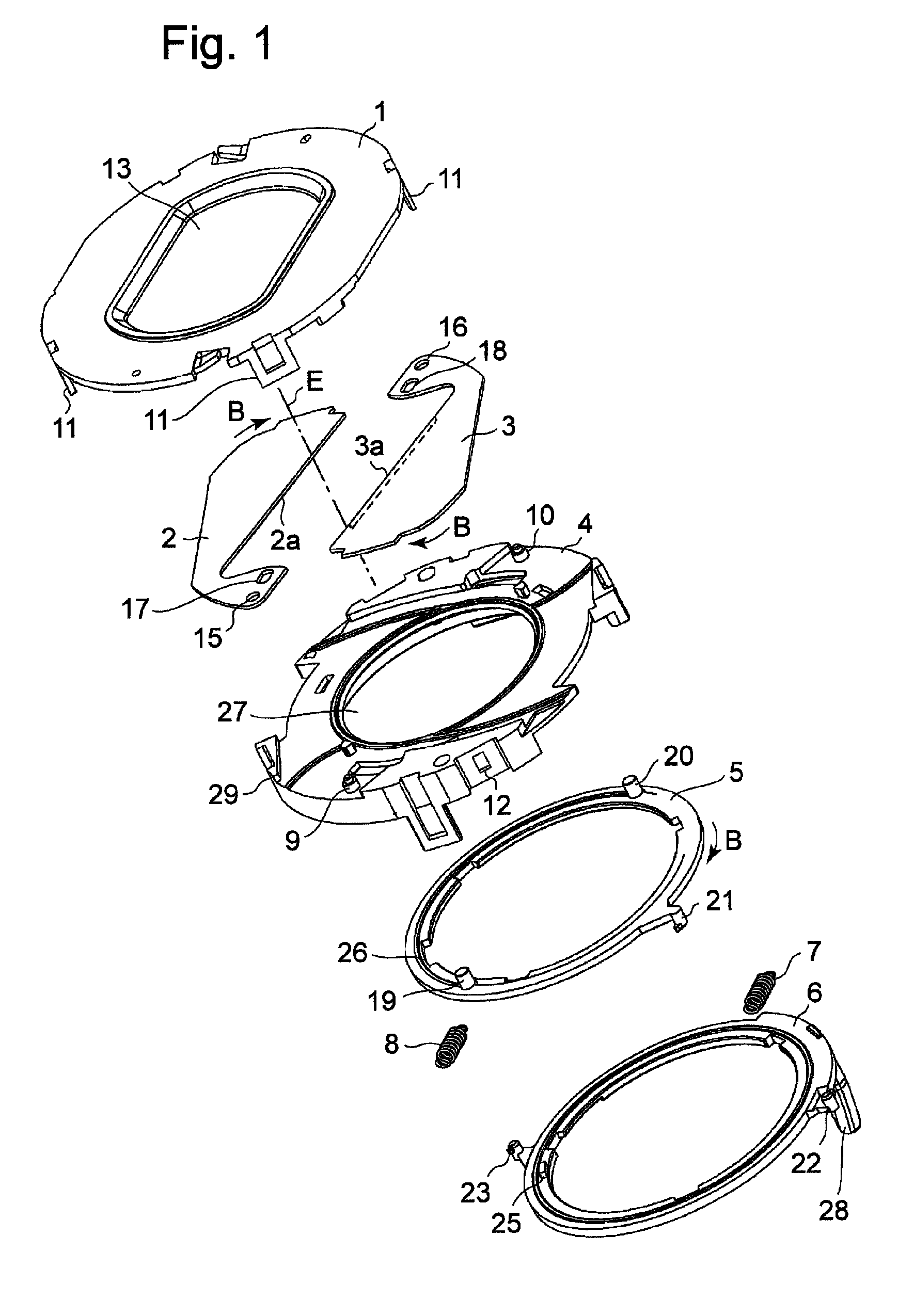
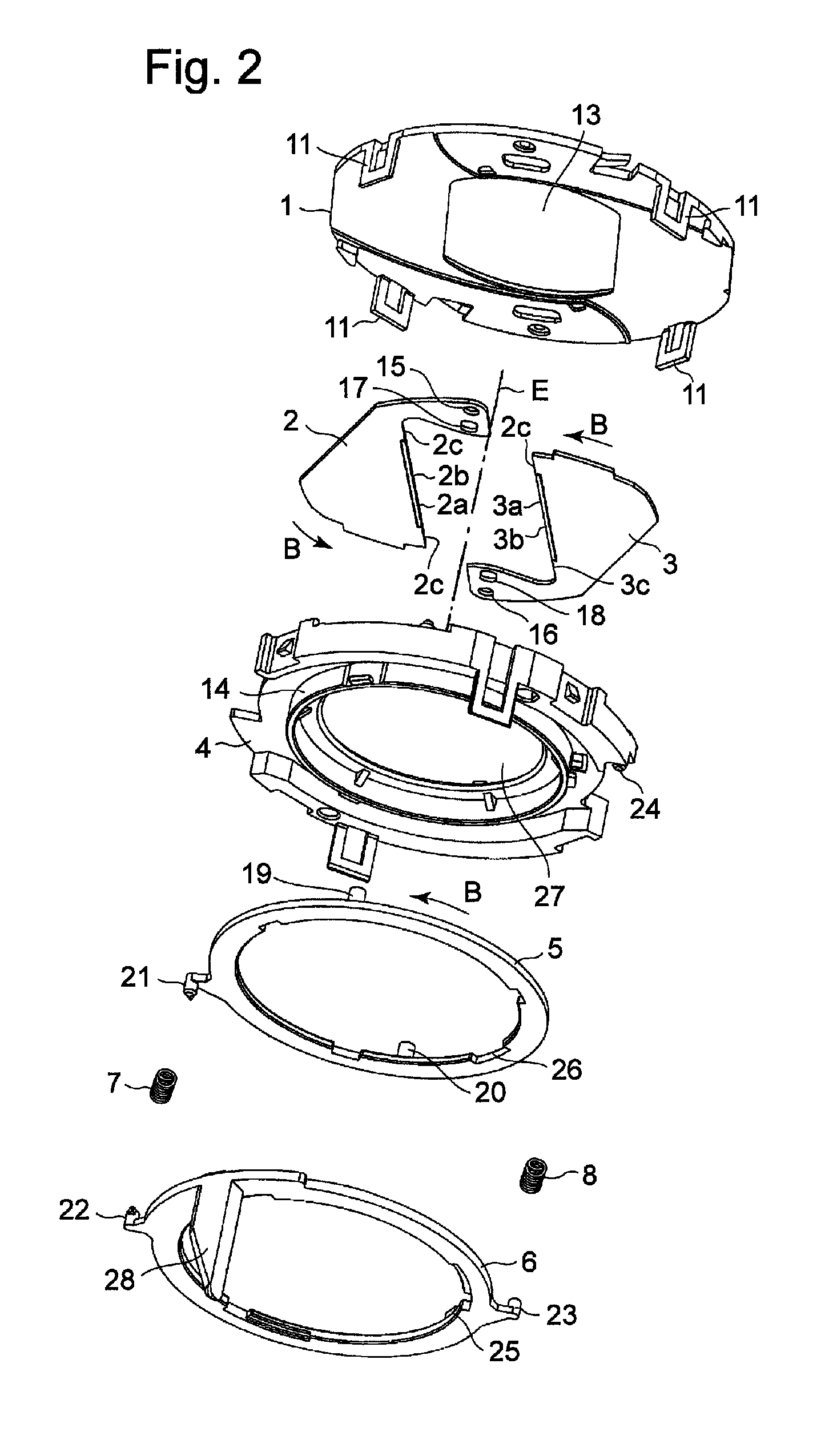
[0026]FIG. 1 is a perspective view seen from a top and showing a configuration of parts of a barrier unit according to a first embodiment. FIG. 2 is a perspective view seen from a bottom and showing the configuration of the parts of the barrier unit according to the first embodiment. FIG. 3 is a plan view of the barrier unit according to the first embodiment being in an open state. FIG. 4 is a plan view of the barrier unit according to the first embodiment being in a closed state. FIG. 5 is a detailed perspective view of first and second blades 2 and 3 of the barrier unit according to the first embodiment. FIG. 6 is a cross-sectional view of the barrier unit according to the first embodiment, with the blades being in an open state (central portions of the respective blades). FIG. 7 is a cross-sectional view of the barrier unit according to the first embodiment, with the blades being in a closed state (the central portions of the respective blades).
[0027]A barrier unit has a cover 1,...
second embodiment
[0041]FIG. 8 is a detailed perspective view of first and second blades 2 and 3 of a barrier unit according to a second embodiment. FIG. 9 is a cross-sectional view of the barrier unit according to the second embodiment, with the blades 2 and 3 being in a closed state (central portions of the respective blades). In the barrier unit according to the second embodiment, as shown in FIG. 8, the thickness t2 of central portions of respective parallel portions 2c and 3c provided on the both sides of inclined portions 2b and 3b is made thicker than the thickness t1 of other portions (the inclined portions 2b and 3b, and portions near the ends, in a longitudinal direction of the inclined portions 2b and 3b). Thus, when the blades 2 and 3 are in a closed state, as shown in FIG. 9, an engageable amount in a thickness direction with the blades 2 and 3 being in a closed state is increased. Hence, even when the positions of the blades 2 and 3 are slightly displaced with respect to each other in t...
third embodiment
[0042]FIG. 10 is a detailed perspective view of first and second blades 2 and 3 of a barrier unit according to a third embodiment. As with the second embodiment, the first and second blades 2 and 3 of the barrier unit according to the third embodiment are also configured such that the thickness t2 of a part of parallel portions 2c and 3c is made thicker than the thickness t1 of other portions. Specifically, by forming protruding portions by pressing out central portions 2d and 3d of the parallel portions 2c and 3c by press molding, portions having the different thicknesses are formed. According to the third embodiment, the first and second blades 2 and 3 having the parallel portions 2c and 3c can be formed using sheet metal by an easy method such as press molding.
PUM
 Abstract
Description
Claims
Application Information
 - R&D
- Intellectual Property
- Life Sciences
- Materials
- Tech Scout
- Unparalleled Data Quality
- Higher Quality Content
- 60% Fewer Hallucinations
Browse by: Latest US Patents, China's latest patents, Technical Efficacy Thesaurus, Application Domain, Technology Topic, Popular Technical Reports.
© 2025 PatSnap. All rights reserved.Legal|Privacy policy|Modern Slavery Act Transparency Statement|Sitemap|About US| Contact US: help@patsnap.com


