Method and device for determining a control scheme for an active power filter

a technology of active power filter and control scheme, which is applied in the direction of electric variable regulation, dc circuit to reduce harmonics/ripples, instruments, etc., can solve the problems of induced thermal stress on the materials within the module, uneven loss distribution, and large design with expensive and weakly utilized semiconductor area. achieve the effect of reducing total losses and balancing

Active Publication Date: 2012-11-29
GENERAL ELECTRIC TECH GMBH
View PDF7 Cites 55 Cited by
  • Summary
  • Abstract
  • Description
  • Claims
  • Application Information

AI Technical Summary

Benefits of technology

[0005]An exemplary embodiment of the present disclosure provides a method for determining a control scheme for a neutral point clamped (NPC) voltage source converter (VSC) with at least 3 levels and a topology of three bridge legs between each of three phases of a grid and a neutral point, each leg including at least four active switches. A clamping carrier modulator is synchronized with the grid for the control of no-switching intervals, and performs the method. The exemplary method includes i) analyzing the waveform of at least one of the grid and a load voltage, and determining windows of 120° within the voltage cycle of the grid / load. The windows are centered around a positive and negative peak maximum of the grid / load voltage waveform, and the windows define an allowed period for no-switching of the corresponding bridge leg. The exemplary method also includes ii) operating and / or simulating an operation of the voltage source converter with a clamping carrier modulator frequency equal to the third harmonic frequency of the grid / load, wherein, if within the window, as a function of the clamping carrier modulator the switching of the corresponding bridge leg is interrupted and clamped, and then analyzing the balance in the operating junction temperatures and / or power losses across the active switches and also analyzing the total losses of the voltage source converter. The exemplary method includes iii) operating and / or simulating the operation of the voltage source converter with a clamping carrier modulator frequency equal to the ninth harmonic frequency of the grid / load, wherein, if within the window, as a function of the clamping carrier modulator, the switching of the corresponding bridge leg is interrupted and clamped, and then analyzing the balance in the operating junction temperatures and / or power losses across the active switches and the total losses of the voltage source converter. In addition, the exemplary method includes iv) comparing the balance and the total losses of steps ii) and iii) and selecting either the clamping carrier modulator frequency according to step ii) or step iii) showing, as primary criterion, the better balance and, as secondary criterion, the lower total losses. The exemplary method also includes v) operating or simulating the operation of the voltage source converter with the selected clamping carrier modulator frequency, wherein as a function of the clamping carrier modulator the switching of the corresponding bridge leg is interrupted and clamped in as far as within the window, while iteratively changing at least one of the following operating parameters of the voltage source converter: switching frequency, DC-link voltage reference, duty cycle of clamping carrier modulator, phase shift of the clamping carrier modulator relative to the grid, and optimising the balance in the operating junction temperatures and / or power losses across the active switches and the total losses of the voltage source converter as a function of the adjustment of these operating parameters until reaching optimum operation parameters for the control scheme.

Problems solved by technology

Especially in 3-level NPC (Neutral Point Clamped) active filters, the commonly irregular load can lead to an uneven loss distribution in the semiconductors of a bridge leg.
In this manner, due to the issue of loss distribution, the usage of these devices often results in an oversized design with expensive and weakly utilized semiconductor area.
The thermal mismatch of components leads to induced thermal stresses on the materials within the module and thermo-mechanical damage could arise.
Consequently, the design of 3-level NPC active filters becomes rather complex as the desired characteristics of high power density, efficiency and component reliability could work against each other.
Due to the unequal distribution of losses and consequent mismatch of junction temperature distribution among the bridge-leg's semiconductors, in the situation of high power converters, for example, the usage of NPC power modules can result in low semiconductor utilization.
However, the usage of different single semiconductors and / or separate heating sinks can result in cost increments and bulky systems.

Method used


Image

  • Method and device for determining a control scheme for an active power filter
  • Method and device for determining a control scheme for an active power filter
  • Method and device for determining a control scheme for an active power filter

Examples


Embodiment Construction

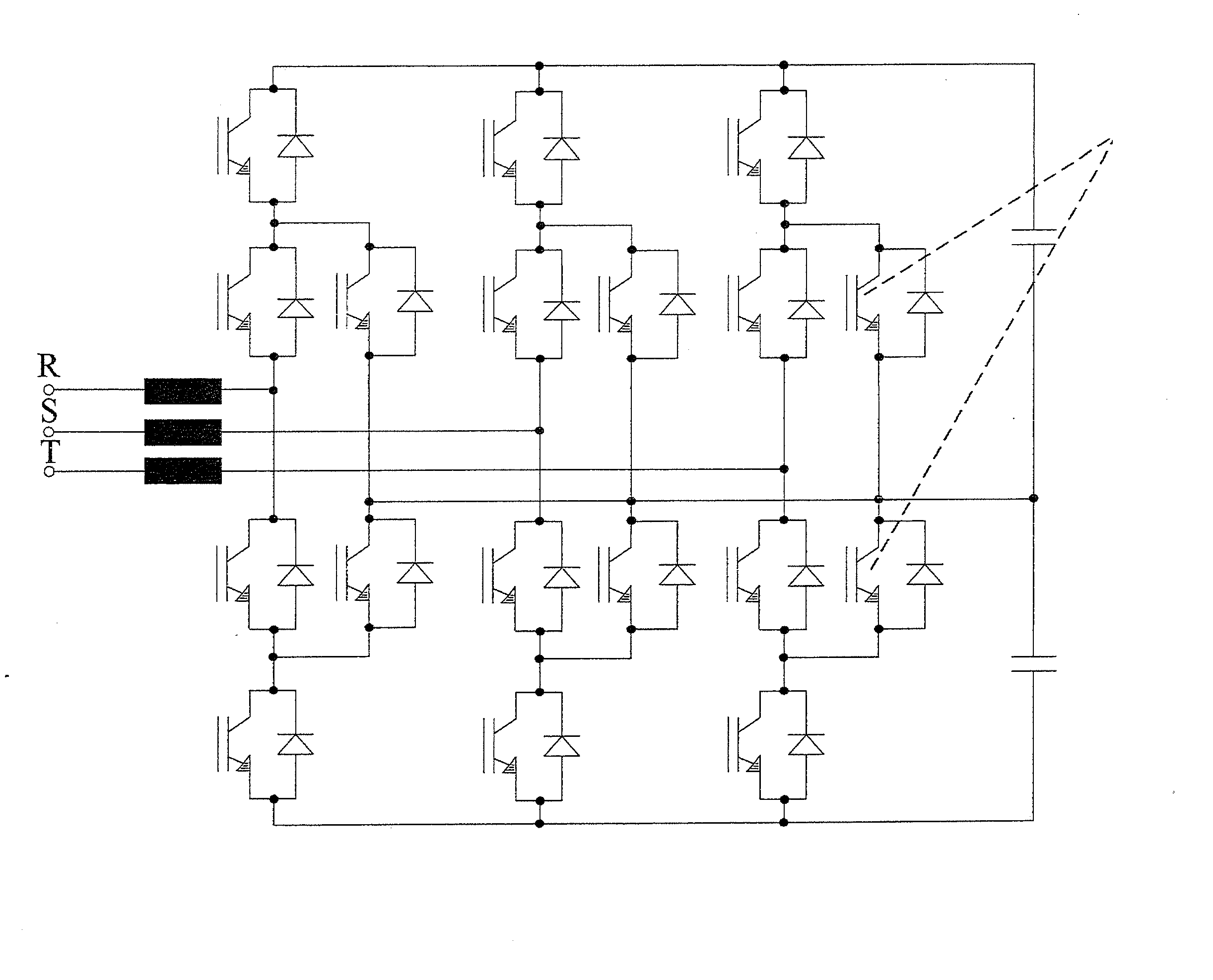
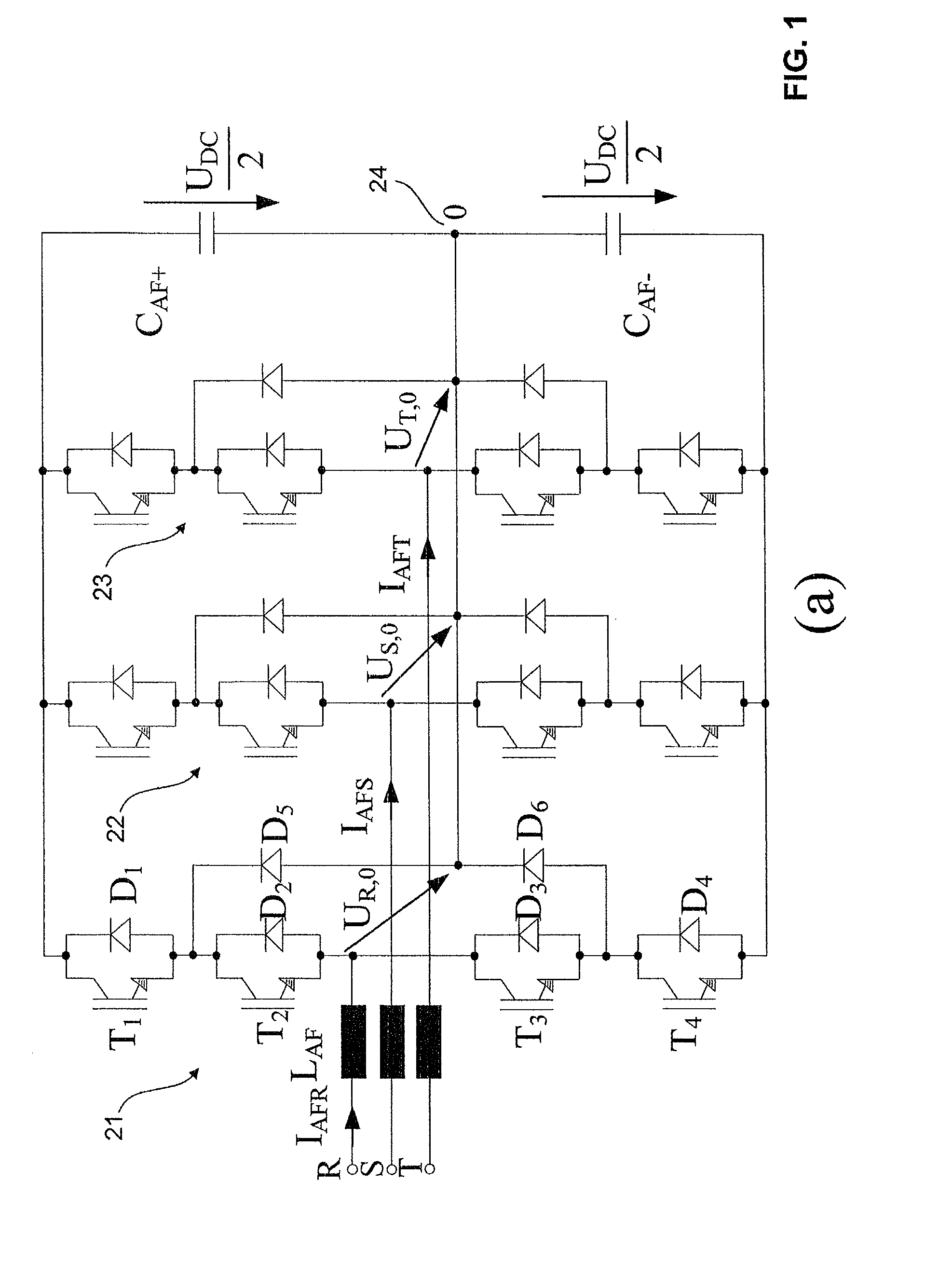
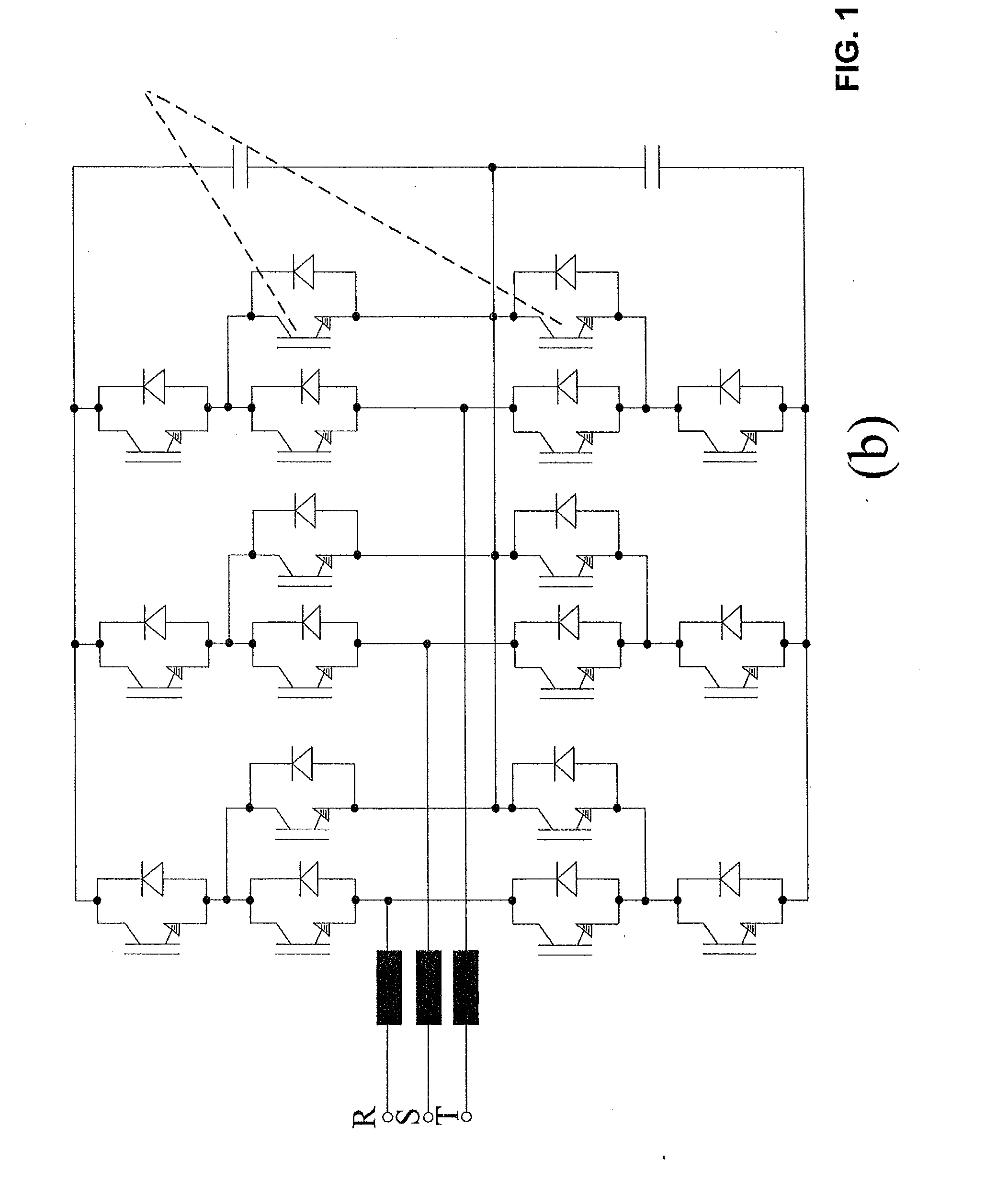
[0015]To address the loss distribution issue of the conventional NPC active filters, while the efficiency of the system is kept high, exemplary embodiments of the present disclosure provide a space vector modulation scheme incorporating an optimal clamping of the phase. With no additional circuitry to the conventional NPC, for most of the typical industrial loads, exemplary embodiments of the present disclosure provide that active filters employing standard commercial NPC bridge leg modules can have their losses well distributed over the chip dies, leading to only a small difference of their operating temperature. In addition, other exemplary embodiments of the present disclosure provide a suitable control method of balancing the DC-link voltages and, to some extent, maintaining the optimal clamping of the currents.

[0016]In accordance with an exemplary embodiment, depending on the current shape of the load compensated by the active filter, the top and bottom DC-link capacitors can b...


PUM


Abstract

A method is provided for determining a control scheme for a neutral point clamped (NPC) voltage source converter (VSC) with at least 3 levels and a topology of three bridge legs between each of three phases of a grid and a neutral point. Each leg includes at least four active switches, and a clamping carrier modulator synchronized with the grid is provided for the control of no-switching intervals. The method includes: analyzing the waveform of the grid and/or a load voltage and determining windows defining an allowed period for no-switching of the corresponding bridge leg; operating or simulating the operation of the voltage source converter with different clamping carrier modulator frequencies, and then analyzing the balance in the operating junction temperatures and/or power losses across the active switches and also analyzing the total losses of the voltage source converter; comparing the balance and the total losses of different clamping carrier modulator frequencies and selecting either the clamping carrier modulator frequency according to showing, as primary criterion, the better balance and, as secondary criterion, the lower total losses; operating or simulating the operation of the voltage source converter with the selected clamping carrier modulator frequency, while iteratively changing at least one of the following operating parameters of the voltage source converter: switching frequency, DC-link voltage reference, duty cycle of clamping carrier modulator, phase shift of the clamping carrier modulator relative to the grid, and optimizing the balance in the operating junction temperatures and/or power losses across the active switches and the total losses of the voltage source converter as a function of the adjustment of these operating parameters until reaching optimum operation parameters for the control scheme.

Description

FIELD[0001]The present disclosure relates to a method for determining a control scheme for an active power filter, such as a neutral point clamped (NPC) voltage source converter (VSC) with at least 3 levels, for example.BACKGROUND INFORMATION[0002]Shunt active power filters are used to minimize the harmonic disturbances created by non-linear loads as they improve the filtering efficiency, and also solve many issues arising with classical passive filters. During the design of such a system, special attention has to be paid to the load currents, which are intended to be compensated. Together with the modulation strategy employed, the load currents are the variables that determine the circulating current in the power devices of the selected Voltage Source Converter (VSC). Especially in 3-level NPC (Neutral Point Clamped) active filters, the commonly irregular load can lead to an uneven loss distribution in the semiconductors of a bridge leg. As in every converter, the losses in the mos...

Claims


Application Information

Patent Timeline
Patent Type & Authority Applications(United States)
IPC IPC(8): H02M1/14H02M1/12
CPCH02J3/1857H02M7/487Y02E40/26Y02E40/20
Inventor KOLAR, JOHANN W.SOEIRO, THIAGORANSTAD, PERLINNER, JORGEN
Owner GENERAL ELECTRIC TECH GMBH
Why Eureka
Try Eureka