Direct field acoustic testing system, controls, and method

a testing system and direct field technology, applied in the field of vibration testing, can solve the problems of real time performance of multiples, limited number of acoustical control inputs and separately controllable outputs, and increase in the number and complexity of calculations required for real time control while a test is being performed, so as to achieve faster real time updates, and faster real time updates

Active Publication Date: 2012-11-29
UNDERWOOD MARCOS
View PDF1 Cites 12 Cited by
  • Summary
  • Abstract
  • Description
  • Claims
  • Application Information

AI Technical Summary

Benefits of technology

[0008]Embodiments hereof also include a MIMO DFAT system with a controller or other processor to provide real time control of the acoustic fields at the control locations. Simplified reference spectrum data is entered based on the relationship of the desired acoustic fields at the control locations. While performing a test only the magnitude component of the drive signals is updated in real time thereby enabling the control means to provide faster real time updates to the drive signals thereby extending the range of controlled frequencies to substantially above 2 kHz for the purpose of producing an acoustic field with pre-specified characteristics.
[0009]Embodiments hereof also include a MIMO DFAT system with equal numbers of separate control inputs and separately controllable outputs. This simplification enables t

Problems solved by technology

However, the use of multiple separately controllable outputs connected to groups of separately driven acoustical transducers combined with the use of multiple microphones to provide separate control inputs leads to a geometric increase in the number and complexity of calculations required for real time control while a test is being performed.
This in combination with the limitations of currently available hardware h

Method used


Image

  • Direct field acoustic testing system, controls, and method
  • Direct field acoustic testing system, controls, and method
  • Direct field acoustic testing system, controls, and method

Examples


Embodiment Construction

[0018]Embodiments hereof are now described with reference to the figures where like reference characters / numbers indicate identical or functionally similar elements. While specific configurations and arrangements are discussed, it should be understood that this is done for illustrative purposes only. A person skilled in the relevant art will recognize that other configurations and arrangements can be used without departing from the spirit and scope of the invention.

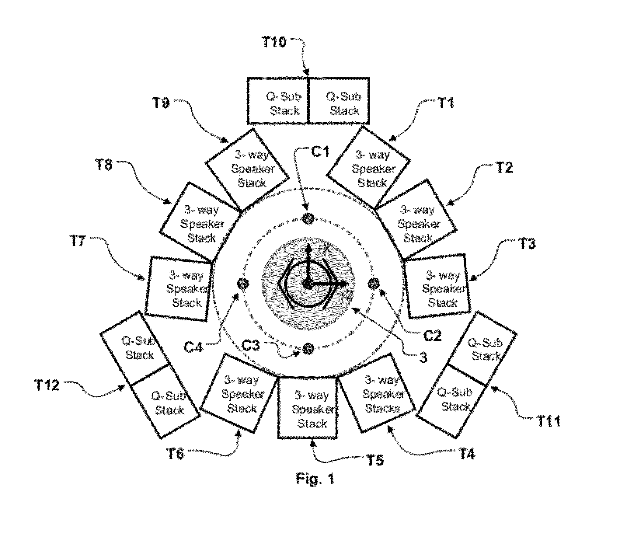
[0019]Referring to FIG. 1, an embodiment of a DFAT system includes a transducer array composed of electro-dynamic acoustic transducers T1-T9 covering various frequency ranges arrayed around the unit under test (UUT) 3 in a generally circular arrangement as shown. The transducer array is composed of three groups three-way speakers T1-T3, T4-T6, T7-T9 generally covering the frequency range above 100 Hz and three groups of electro-dynamic subwoofer loudspeakers T10-T12 generally covering the frequency range from 20 Hz to 200...


PUM


Abstract

A direct field acoustic testing system includes at least one control microphone, a controller operatively coupled to the control microphone such that the controller receives at least one input signal from the control microphone, and at least four acoustic transducer groups operatively coupled to the controller such that each transducer is separately controllable by the controller such that a separate output signal is received by each transducer from the controller. A setup signal is applied to each of the acoustical transducers. The acoustic output of each of the acoustical transducers is monitored using the at least one control microphone. Assumptions regarding the relationship between the acoustic fields measured by the control microphones are made to enable the controller to reduce the number of calculations needed to compute error functions and corrected drive signals to be applied to the acoustic transducer groups.

Description

BACKGROUND OF THE INVENTION[0001]1. Field of the Invention[0002]The present invention relates generally to the field of vibration testing of objects such as satellites, instrumentation or any other object whose reliability in operation may be evaluated using high intensity vibration testing. Specifically, the present invention relates to the use of direct field acoustic systems to perform vibration testing and to control means to increase the control bandwidth of direct field acoustic test systems having multiple outputs connected to separately driven groups of acoustical transducers.[0003]2. Background of the Invention[0004]The disclosure of co-pending U.S. application Ser. No. 13 / 117,870 filed May 27, 2011 (attorney docket no. MSI001) is incorporated by reference herein in its entirety.[0005]As disclosed in co-pending U.S. application Ser. No. 13 / 117,870 filed May 27, 2011 (attorney docket no. MSI001) direct field acoustic test (DFAT) systems employing multiple separately controll...

Claims


Application Information

Patent Timeline
IPC IPC(8): H04B17/00
CPCG01M7/00G01N29/04
Inventor UNDERWOOD, MARCOS A.GOLDSTEIN, ROBERT TURKLARKIN, PAUL ALAN
Owner UNDERWOOD MARCOS
Why Eureka
Try Eureka