Sound outputting device

a sound output device and sound technology, applied in piezoelectric/electrostrictive transducers, active noise control, instruments, etc., can solve problems such as putting a burden on the ear

Active Publication Date: 2012-11-29
KYOCERA CORP
View PDF15 Cites 101 Cited by
  • Summary
  • Abstract
  • Description
  • Claims
  • Application Information

AI Technical Summary

Problems solved by technology

Such a configuration may p

Method used


Image

  • Sound outputting device
  • Sound outputting device
  • Sound outputting device

Examples


Embodiment Construction

[0025]Exemplary embodiments of the present invention will be explained in detail below with reference to the accompanying drawings. It should be noted that the present invention is not limited by the following explanation. In addition, this disclosure encompasses not only the components specifically described in the explanation below, but also those which would be apparent to persons ordinarily skilled in the art, upon reading this disclosure, as being interchangeable with or equivalent to the specifically described components.

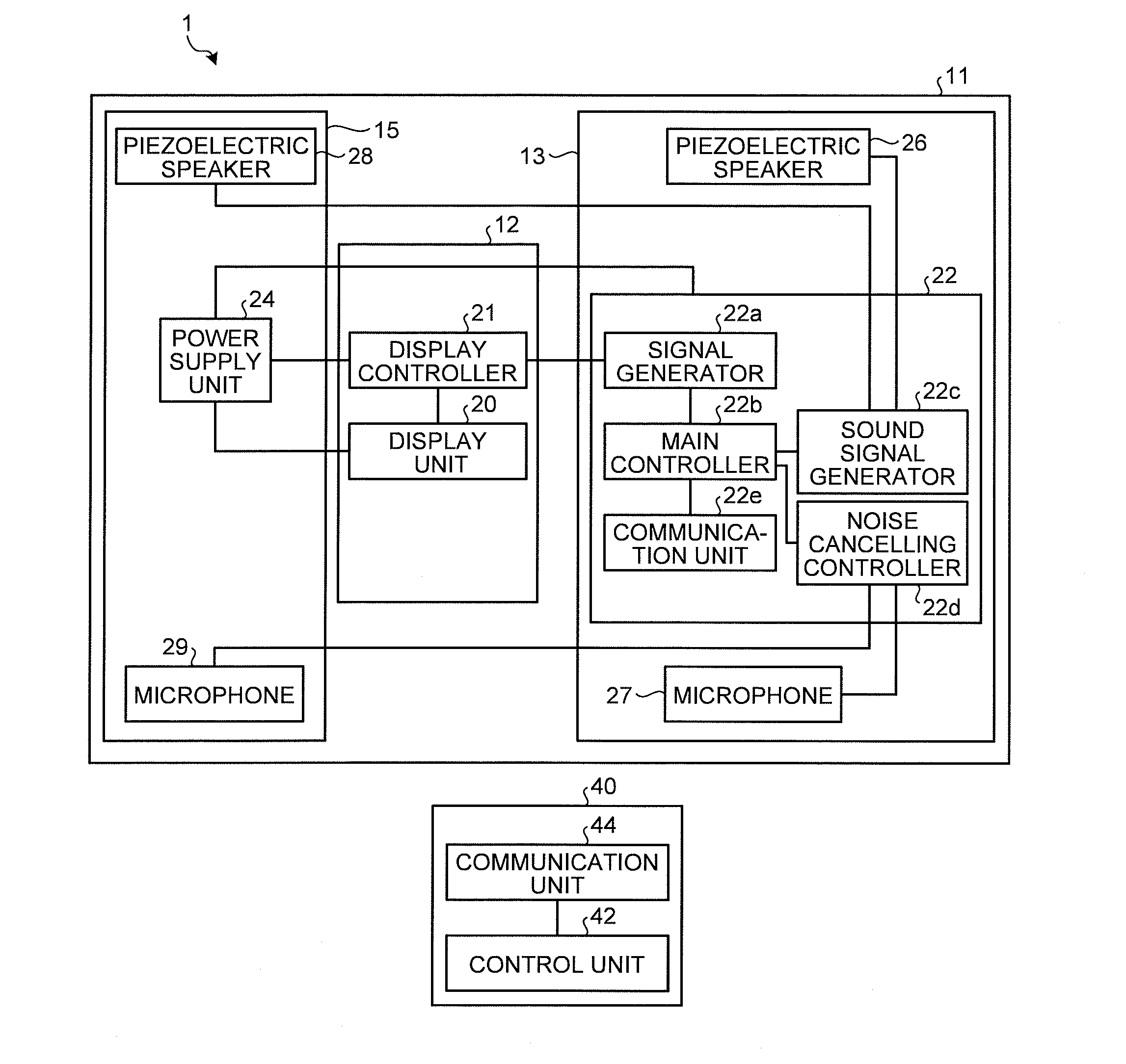
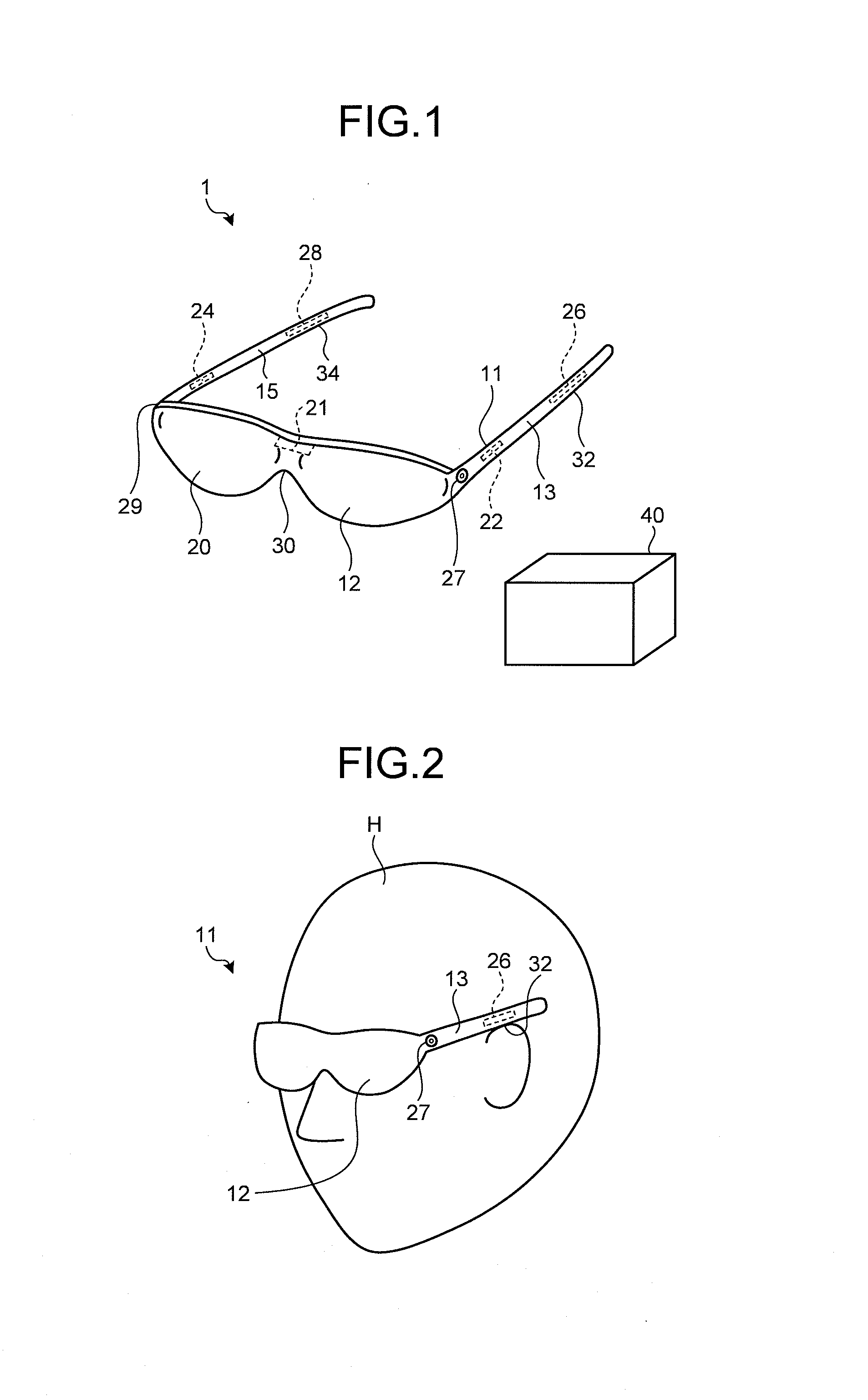
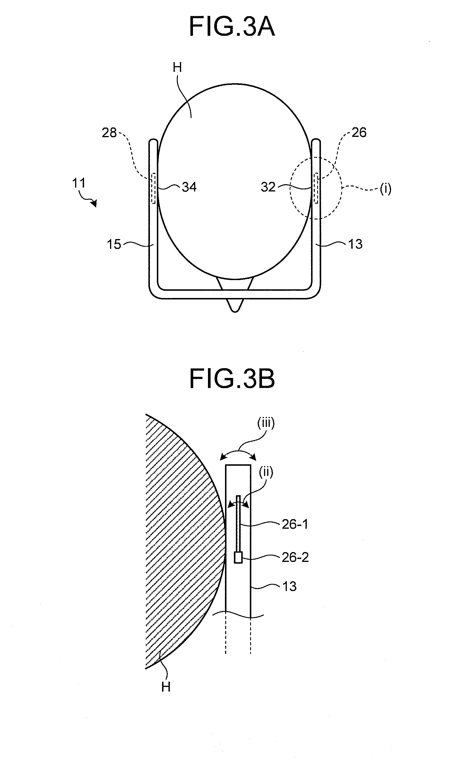
[0026]FIG. 1 is a perspective view illustrating a schematic configuration of an image and sound output system 1 including a sound outputting device according to an embodiment. FIG. 2 is an explanatory perspective view illustrating a sound outputting device 11 mounted on user H. The image and sound output system 1 in FIG. 1 includes the sound outputting device 11 and a control unit 40. The image and sound output system 1 according to the embodiment represent an...


PUM


Abstract

According to an aspect, a sound outputting device includes a front unit, a first side unit, a second side unit, a sound transmitting portion, and a piezoelectric speaker. The first side unit is coupled to one end portion of the front unit. The second side unit is coupled to another end portion of the front unit. The sound transmitting portion is provided in the first side unit for transmitting a sound via cartilage conduction. The piezoelectric speaker vibrates the sound transmitting portion.

Description

CROSS-REFERENCE TO RELATED APPLICATIONS[0001]This application claims priority from Japanese Application No. 2011-119545, filed on May 27, 2011, the content of which is incorporated by reference herein in its entirety.BACKGROUND[0002]1. Technical Field[0003]The present disclosure relates to a sound outputting device (headset) that is configured to be mounted on user's head.[0004]2. Description of the Related Art[0005]Conventionally, eyeglass-shaped headsets using wireless communication have been disclosed (see for example, Japanese Patent Application National Publication (Laid-Open) No. 2005-534269).[0006]Some headset is configured such that an earphone using a dynamic speaker is inserted into user's ear when he / she use the audio headset. Such a configuration may put a burden on his / her ear.[0007]For the foregoing reasons, there is a need for a sound outputting device that reduces a burden on a user's ear.SUMMARY[0008]According to an aspect, a sound outputting device includes a front...

Claims


Application Information

Patent Timeline
IPC IPC(8): G10K11/16H04R1/02H04R17/00
CPCG02C11/10H04R25/43H04R1/1083H04R5/033H04R5/0335H04R17/00H04R25/55H04R25/606G10K2210/1081G10K2210/3028H04R2225/31H04R2460/01H04R2460/13H04R2499/11G10K11/1786G10K11/17821G10K11/17823G10K11/1783G10K11/17837G10K11/1785G10K11/17857G10K11/17873H04R1/028
Inventor HORII, SEIJI
Owner KYOCERA CORP
Why Eureka
Try Eureka