Motion and vibration cuing system

a cuing system and vibration technology, applied in the field of motion simulators, can solve the problems of difficult and expensive installation of systems such as the size and complexity of current full flight simulators, extreme physical size and substantial cost, and extreme physical size of the typ

Active Publication Date: 2012-11-29
IND SMOKE & MIRRORS
View PDF14 Cites 22 Cited by
  • Summary
  • Abstract
  • Description
  • Claims
  • Application Information

AI Technical Summary

Benefits of technology

[0007]The frame actuators that support the frame assembly are effective to produce six degrees-of-freedom of motion, including surge, sway, heave, roll, pitch and yaw, as well as vibration. The motion seat(s) produce surge, sway, heave and roll motions. Collectively, the frame actuators and motion seat(s) provide the pilot with the sensation of movement through his or her tactile interface with the motion seat, as well as a visual indication of the corresponding movement of the cockpit created by the actuators acting on the frame assembly, in order to closely replicate the maneuver which the user is performing using the instrumentation of the aircraft and / or any external aerodynamic forces being applied to the aircraft.

Problems solved by technology

Significant limitations of current full flight simulators of the type described above include their extreme physical size and substantial cost.
A huge facility is required to house such simulators, and it is challenging and expensive to install systems of such size and complexity.
Further, full flight simulators typically cost between one and three million dollars (US), not including the cost of the cockpit control and OTW systems.

Method used


Image

  • Motion and vibration cuing system
  • Motion and vibration cuing system
  • Motion and vibration cuing system

Examples


Embodiment Construction

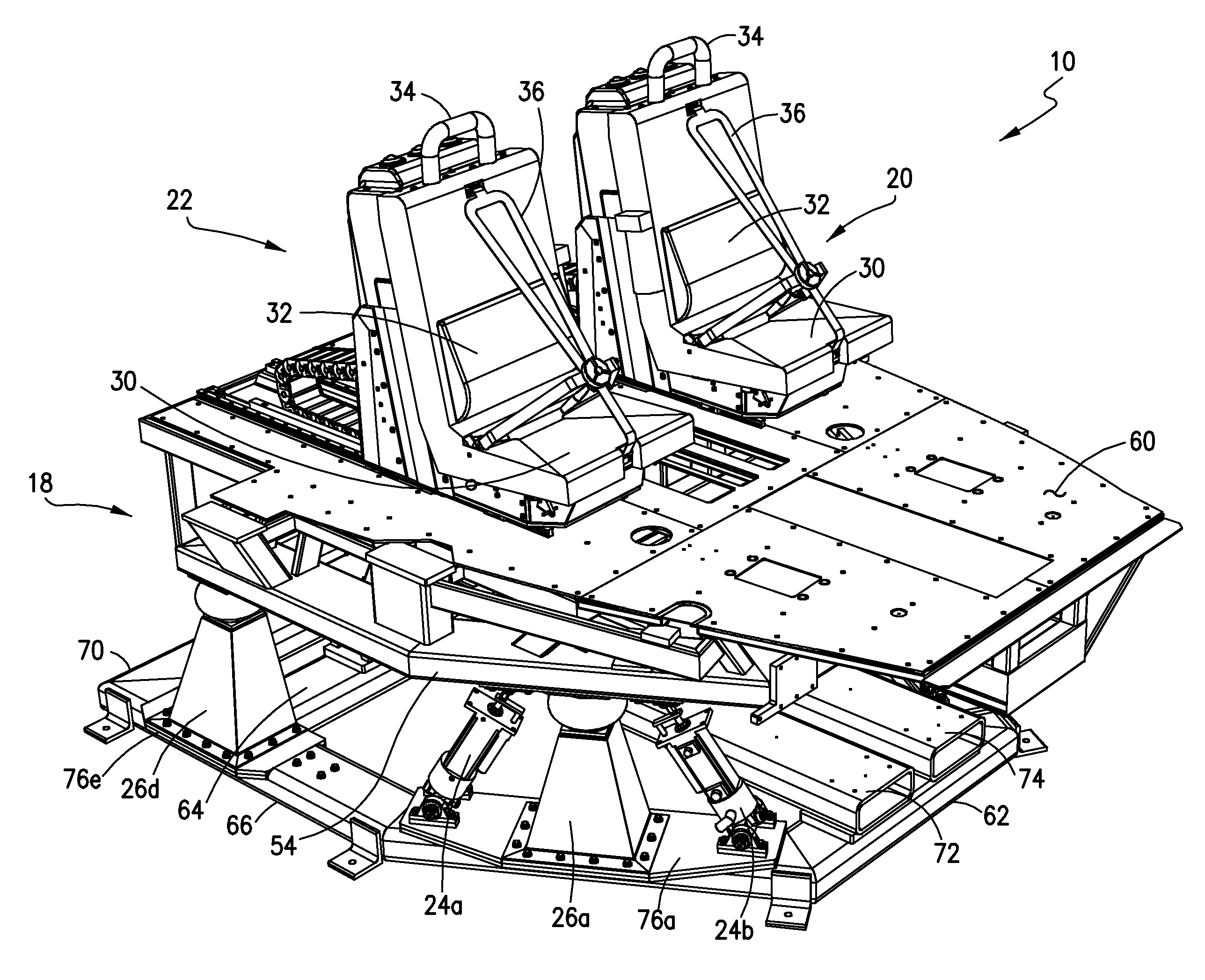
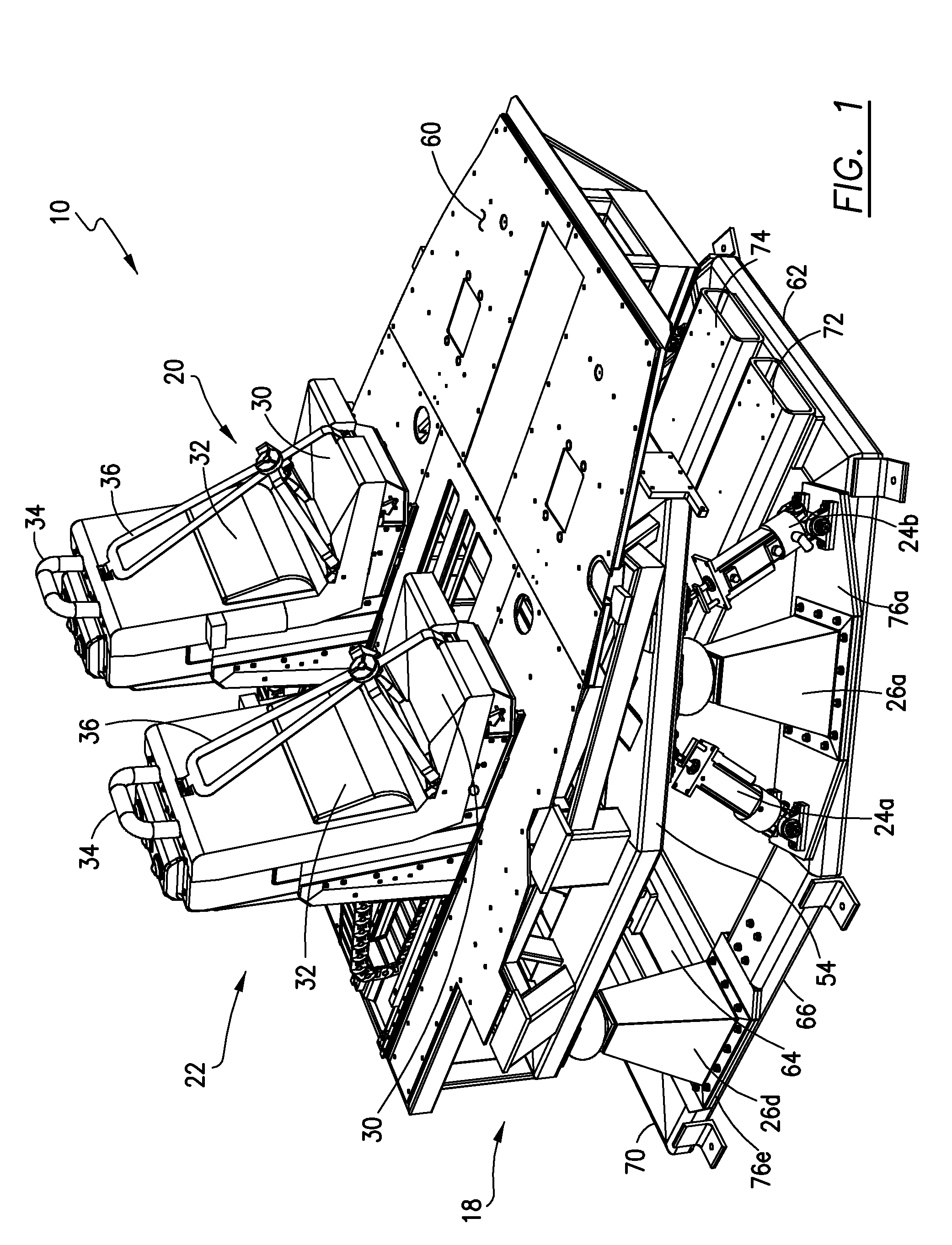
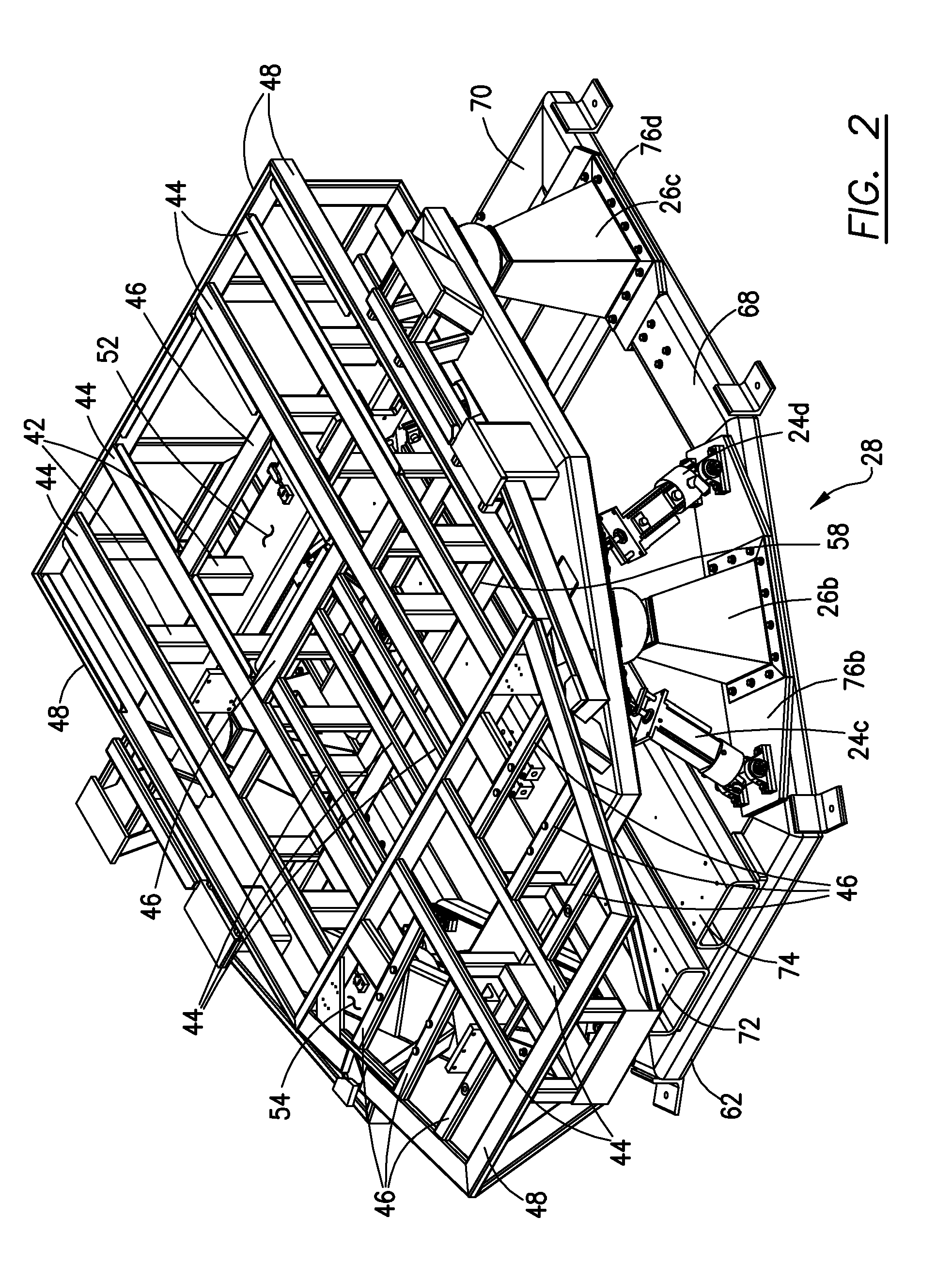
[0017]Referring initially to FIGS. 1 and 6, a motion and vibration cuing system 10 according to this invention is illustrated. The system 10 is adapted for use as part of motion simulation system (not shown) for a particular type of vehicle. For purposes of the present discussion, a full flight simulation system for aircraft is described herein but it should be understood that the system 10 may be employed with land vehicles and / or water vehicles. Further, the term “aircraft” is meant to broadly refer to fixed wing, rotary and hover craft.

[0018]Full flight simulation systems may include a cockpit with highly detailed replications of all of the flight controls and aircraft systems of a particular type of aircraft, as well as an OTW system which provides the user or pilot with a visual indication of what he or she would be seeing during flight. All of these components are commercially available and their details form no part of this invention and are therefore not discussed herein. As...


PUM


Abstract

A motion and vibration cuing system for use with a motion simulator provides vibratory, impulse, onset and sustained motion cuing, independently or simultaneously, by operation of a frame assembly capable of producing vibration and six degrees-of-freedom of motion in coordination with one or more motion seats, mounted to the frame assembly, which produce surge, sway, heave and roll motions.

Description

FIELD OF THE INVENTION[0001]This invention relates to motion simulators for aircraft, land vehicles and water vehicles, and, more particularly, to a motion and vibration cuing system for providing vibratory, impulse, onset and sustained motion cuing wherein the movement of motion seats is coupled to the movement of a frame assembly upon which the motion seats are mounted.BACKGROUND OF THE INVENTION[0002]One of the most common motion simulation systems in use today are flight simulators which re-create aircraft flight and different aspects of the flight environment. Flight simulators are employed for flight training, the design and development of aircraft, control handling evaluation and other purposes. Depending on the purpose of a particular device, flight simulators can range in complexity from PC-laptop models to full flight simulators employing replicas of an aircraft cockpit including controls, aircraft systems and wide-field outside-world (OTW) visual systems all mounted on si...

Claims


Application Information

Patent Timeline
Patent Type & Authority Applications(United States)
IPC IPC(8): G09B19/16
CPCG09B9/14
Inventor GARVIS, ANDREW W.WILHELM, DENNIS P.JOHNSON, RICHARD E.LANSRUD, STEVEN G.
Owner IND SMOKE & MIRRORS
Why Eureka
Try Eureka