Inground Pool Wall and Deck Support

Inactive Publication Date: 2012-12-06
SIRCO COLLIN J
View PDF5 Cites 0 Cited by
  • Summary
  • Abstract
  • Description
  • Claims
  • Application Information

AI Technical Summary

Benefits of technology

[0008]It is another object and advantage of the present invention to provide support structure for concrete decking that is adjustable to accommodate pool walls of varying heights.
[0009]It is a further object and advantage of the present invention to provide support structure for concrete decking that may be used with straight or curved pool walls and with walls composed of different materials.
[0010]Other objects and advantages of the present invention will in part be obvious and in part appear hereinafter.
[0011]In accordance with the foregoing objects and advantages, the present invention provides a pool wall and deck support member comprising modular and symmetrical upper and lower halves adapted to be interconnected to one another to form the unitary support member. Each half is essentially V-shaped with the bottom of the V having a pair of fastening elements disposed thereon and adapted to securely engage corresponding fastening elements disposed on the bottom of the V of the opposite half. Disposed on the ends of the upwardly extending legs of the V-shaped members are fastening elements that are adapted to engage a cross bar that extends across the V-shaped member. While each half of the V-shaped members are approximately equal to half the height of a standard pool wall (e.g., about 21 inches each), extension modules having correspondingly shaped and positioned fastener elements disposed o

Problems solved by technology

If the decking is poured prior to the backfill being fully settled, cracking and breaking of the concrete deck will likely occur causing the deck to slip

Method used


Image

  • Inground Pool Wall and Deck Support
  • Inground Pool Wall and Deck Support
  • Inground Pool Wall and Deck Support

Examples


Example

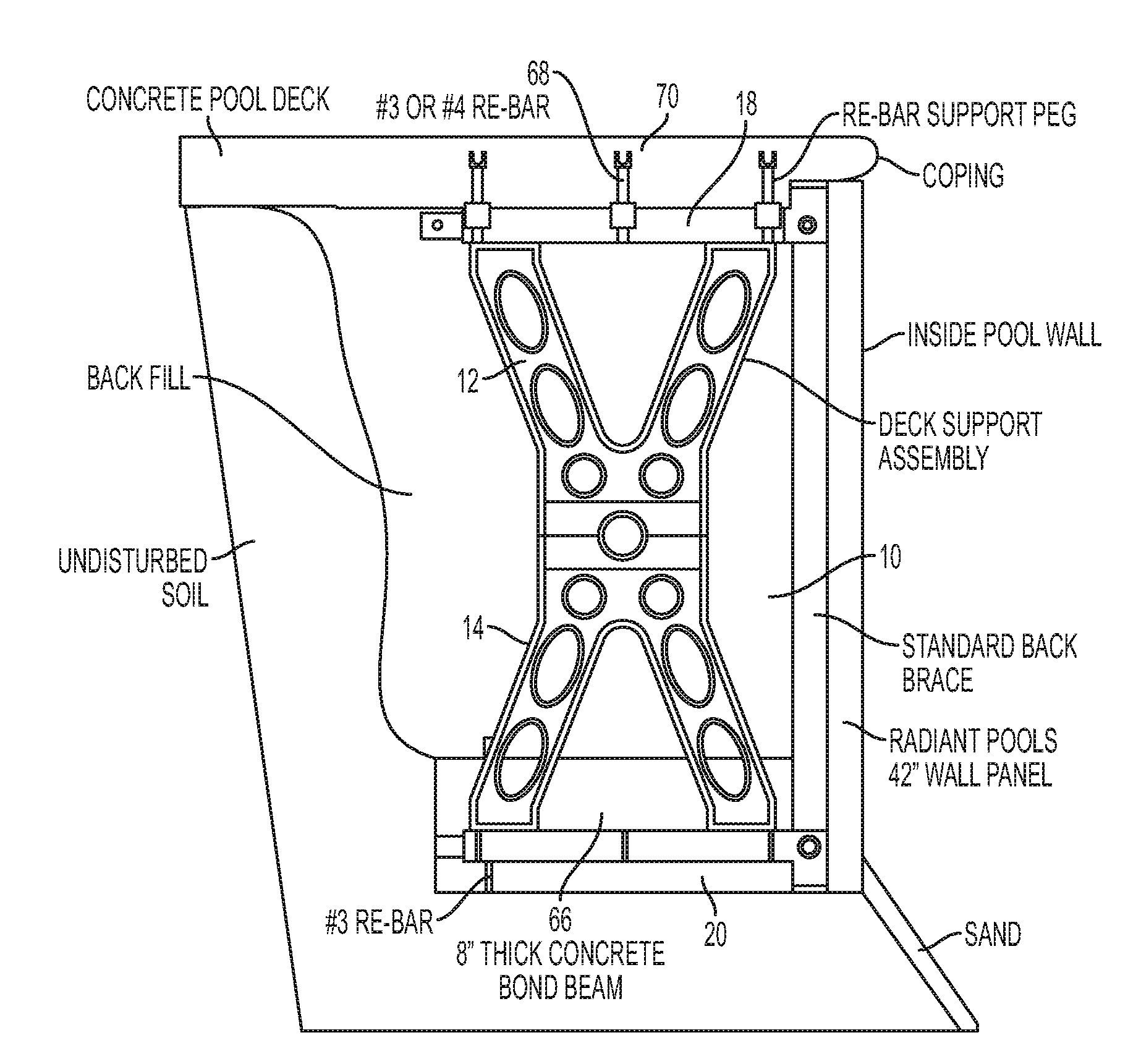
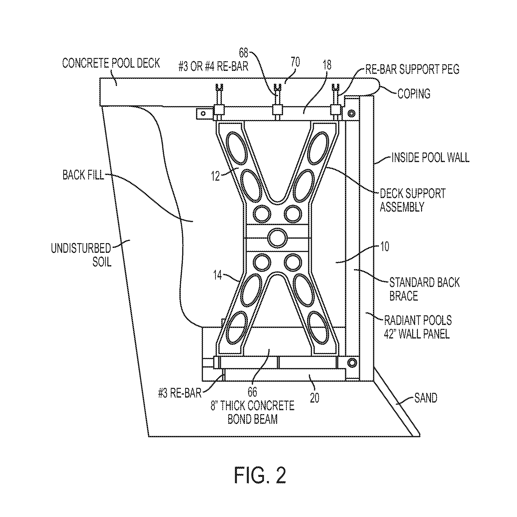
[0036]Reference being had to the drawings, wherein like reference numerals refer to like parts throughout, there is seen in FIG. 3. among others, a generally X-shaped pool wall and deck support member, designated generally by reference numeral 10, comprising modular and symmetrical, upper and lower V-shaped elements 12, 14, respectively, interconnected to one another at their respective vertices to form the X-shaped support member 10. With reference to FIGS. 3, 5 and 6, one or more extension modules 16 may be interconnected between the V-shaped elements 12 and 14 to extend the height of the support member 10 and accommodate pool walls of varying heights. Support member 10 further comprises upper and lower cross members 18 and 20, respectively, which extend in a common plane with support member 10 and between the terminal ends of the upper and lower elements 12 and 14, respectively.

[0037]Each element 12 and 14 includes a male and female connector / fastening element 22, 24, respectivel...


PUM


Abstract

The present invention provides a pool wall and deck support member including modular and symmetrical upper and lower halves adapted to be interconnected to one another to form a unitary support member. Each half is essentially V-shaped with the bottom of the V having a pair of fastening elements disposed thereon and adapted to securely engage corresponding fastening elements disposed on the bottom of the V of the opposite half. Disposed on the ends of the upwardly extending legs of the V-shaped members are fastening elements that are adapted to engage a cross bar that extends across the V-shaped member.

Description

CROSS REFERENCE TO RELATED APPLICATION[0001]The present application claims priority to U.S. Provisional Patent Application Ser. No. 61 / 492,528, filed Jun. 2, 2011, the entirety of which is hereby incorporated by reference.BACKGROUND OF THE INVENTION[0002]1. Field of the Invention[0003]The present invention relates generally to support structures for the walls and decking that define an inground swimming pool.[0004]2. Description of the Related Art[0005]Construction of an inground swimming pool involves excavating the land area where the swimming pool is to be located. Typically, the excavation extends for about 2-3 feet beyond the outer dimensions of where the pool's walls will be fixed in place. Once the hole is dug, the walls that provide the structural rigidity and shape to the pool are set in position and interconnected to one another. As shown in FIG. 1, an A-Frame brace is then set against the exterior surface of each wall to maintain the walls plumb. A concrete bond beam is p...

Claims


Application Information

Patent Timeline
IPC IPC(8): E04H4/14
CPCE04H4/14E04H2004/0068E04H4/141E04H4/0087
Inventor FOSTER, CHARLES M.STEELE, DAVID A.SIRCO, COLLIN J.
Owner SIRCO COLLIN J
Why Eureka
Try Eureka