Method and apparatus for fitting of a plug housing

a plug and housing technology, applied in the direction of electrical programme control, program control, instruments, etc., can solve the problems of not always being able to ensure the precise and error-free fitting of the contact portion to the plug housing

Active Publication Date: 2012-12-06
APTIV TECH LTD
View PDF1 Cites 14 Cited by
  • Summary
  • Abstract
  • Description
  • Claims
  • Application Information

AI Technical Summary

Benefits of technology

[0028]According to yet another advantageous embodiment of the invention, the steps in the method to calibrate the control unit of the moveable robot as previously described above is performed at least once with a reference object mounted on a flange of the robot and at least once with one on a gripping device of the robot mounted on the flange of the robot. By the above-mentioned method, the position and orientation of a gripper relative to a position and orientation of the robot flange can be determined in three-dimensional coordinates, although a spatially resolved picture contains only an image in two coordinates. This information can subsequently be used by the control unit to approach a predetermined position with the gripping device exactly. In this case, the same reference object can be used in particular for the flange of the robot and for the gripping device. In this case an imprecise shape of the reference object has no effect on the precision of measurement, because in both steps essentially the same measurement errors are made, and these are therefore compensated when determining the relative position of robot flange and gripping device.

Problems solved by technology

In particular, if robots, plug housings, holders, and contact portions are used, which are respectively subject to manufacture-related mechanical tolerances, a precise, error-free fitting of the contact portion to the plug housing may not always be guaranteed.

Method used


Image

  • Method and apparatus for fitting of a plug housing
  • Method and apparatus for fitting of a plug housing
  • Method and apparatus for fitting of a plug housing

Examples


Embodiment Construction

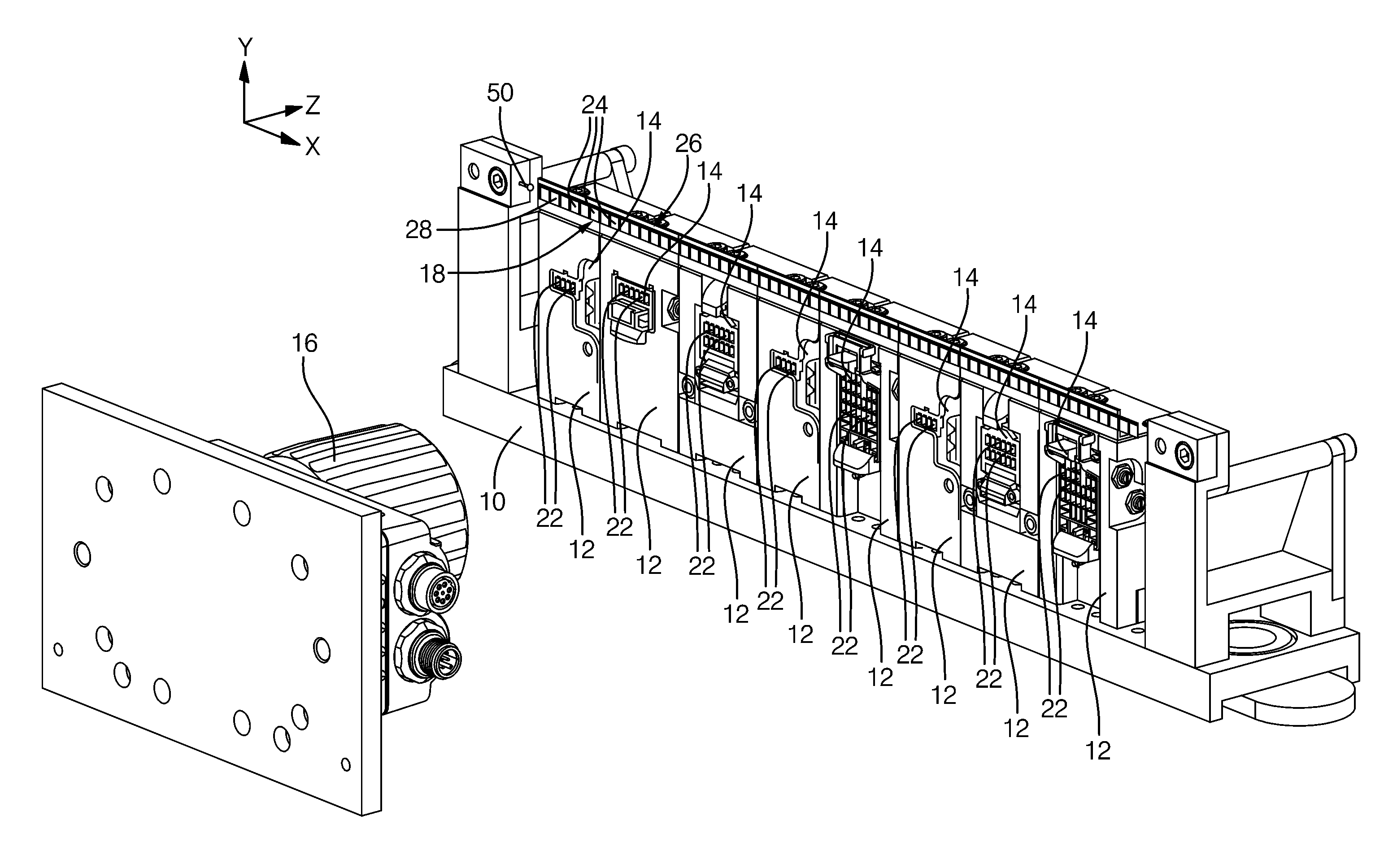
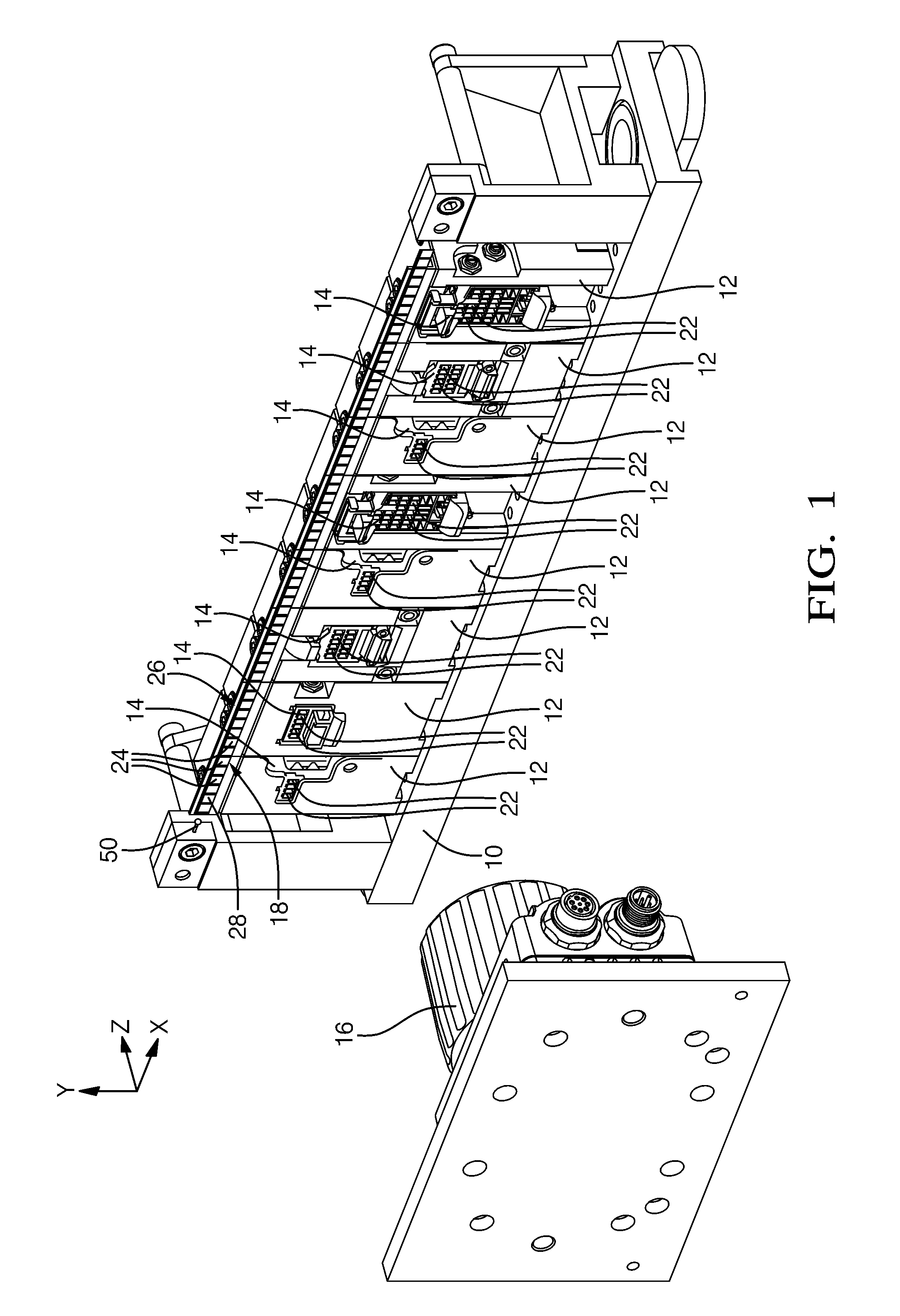
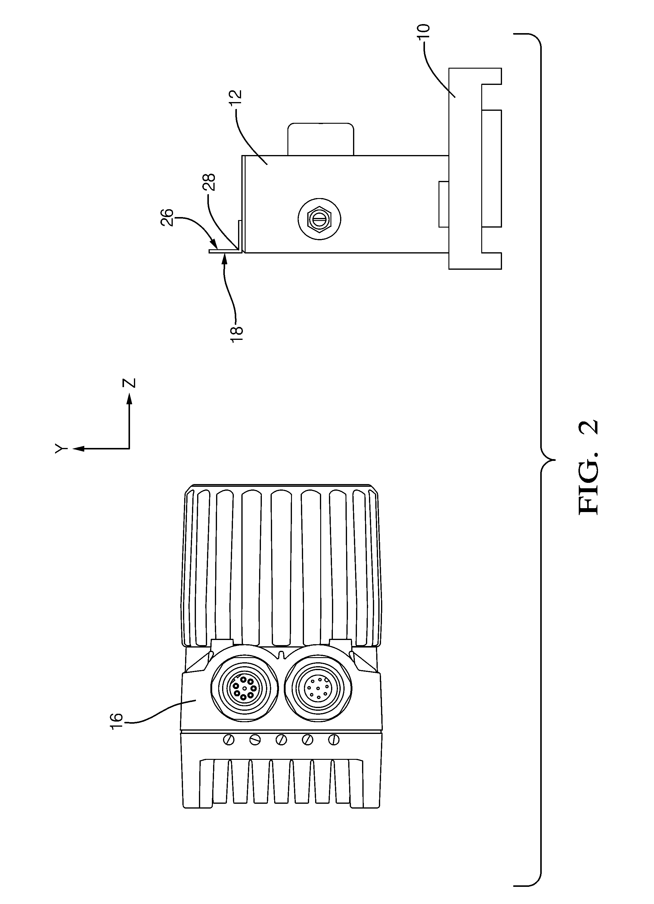
[0043]In accordance with a one embodiment of this invention, referring to FIG. 1, shows a perspective view of an assembly apparatus according to an embodiment of the invention. The apparatus includes a holder 10 with several holding devices 12 in each of which a plug housing 14 is fixed by latching. The holding devices 12 of the holder 10 are arranged succeeding each other in a longitudinal direction x of the holder 10, and releasably connected to a base section of the holder 10. A first optical detection device 16 is directed onto a rear side 26 of the holder 10, from which a contact portion 20, as best illustrated in FIG. 4, is inserted in a plug cavity 22 of a plug housing 14. Device 16 is configured to take a spatially resolved picture which contains holder 10 and plug housing 14.

[0044]The holder 10 comprises several reference features 24 which are designed as data matrix codes and which are arranged on a support 28 at regular intervals succeeding each other in the longitudinal ...


PUM

PropertyMeasurementUnit
mechanicalaaaaaaaaaa
movementaaaaaaaaaa
optical measurementaaaaaaaaaa

Abstract

A method to fit a contact portion in a plug housing by a robot is presented. Steps in the method include attaching a plug housing to a holder and gripping the contact portion by a gripping device of the robot. Other steps in the method include taking at least one spatially resolved picture by at least one optical detection device such that the plug housing and the contact portion are contained in the picture, determining a respective position of the plug housing and the contact portion in the picture by a control unit of the moveable robot, calculating a robot movement by the control unit that is a function of the determined positions, and performing the calculated movement by the robot to fit the contact portion in the plug housing. An apparatus to perform the method and another method to calibrate the control unit of the robot are also presented.

Description

RELATED DOCUMENTS[0001]This application claims priority to European application EP 10015198.4 filed on 1 Dec. 2010.TECHNICAL FIELD[0002]This invention relates to a method and an apparatus for the fitting of a plug housing with a contact portion mounted on an electrical cable by a movable robot as well as a method for the calibration of a control unit of a movable robot.BACKGROUND OF INVENTION[0003]It is known to have a plug housing fixed to a holder, and an electrical cable with a contact portion gripped by a robot, and a spatially resolved picture of the plug housing taken by an optical detection device. By evaluation of the picture of the plug housing, it may be detected when the plug housing is accidentally mounted with a tilt or offset from its desired standard position in the holder so that a correction of a relative position of the plug housing in relation to the robot may be made.[0004]In particular, if robots, plug housings, holders, and contact portions are used, which are ...

Claims


Application Information

Patent Timeline
Patent Type & Authority Applications(United States)
IPC IPC(8): B23P11/00G05B19/04
CPCG01B11/002H01R43/20B25J9/162B25J9/1687G05B2219/40033Y10T29/49208Y10T29/49147Y10T29/49826Y10T29/5136Y10T29/5137G05B2219/40298
Inventor LARISCH, MARKUS
Owner APTIV TECH LTD
Why Eureka
Try Eureka