Eye tracking system for use in head-mounted display units

a technology of eye tracking and display unit, which is applied in the direction of mechanical pattern conversion, optical elements, instruments, etc., can solve the problems of high energy demand, affecting the comfort of wearing hmd, and the weight of the eye tracking modul

Active Publication Date: 2022-02-17
INSEYE INC
View PDF8 Cites 4 Cited by
  • Summary
  • Abstract
  • Description
  • Claims
  • Application Information

AI Technical Summary

Benefits of technology

[0008]In yet another embodiment of the present invention, a non-transitory computer-readable storage media having computer-executable instructions embodied thereon for operating an eye tracking system mounted to an HMD unit is provided. The eye tracking system includes a light source configured to illuminate an area of a subject's eye, a plurality of photosensors configured to receive reflected light from different portions of the illuminated eye, a temperature sensor configured to measure a temperature of the photosensors, and a processor. When executed by the processor, the computer-executable instructions cause the processor to perform an algorithm including a processing module that compensates photosensor measurement error due to variable operating temperature in the HMD unit, and an eye-tracking module that determines a gaze position of the eye using a mapping between intensities of photosensors and a gaze position estimated during a calibration procedure.

Problems solved by technology

However, this solution is burdened with problems such as: 1) Complicated assembling, often using IR mirrors directing IR light reflected from the eyes onto the camera lens; 2) IR cameras are relatively expensive; 3) Total weight of the eye tracking module significantly affects the HMD wearing comfort; 4) Heat emission may require an additional cooling system; 5) High energy demand; and 6) Computing power consuming dedicated for image processing.

Method used


Image

  • Eye tracking system for use in head-mounted display units
  • Eye tracking system for use in head-mounted display units
  • Eye tracking system for use in head-mounted display units

Examples


Embodiment Construction

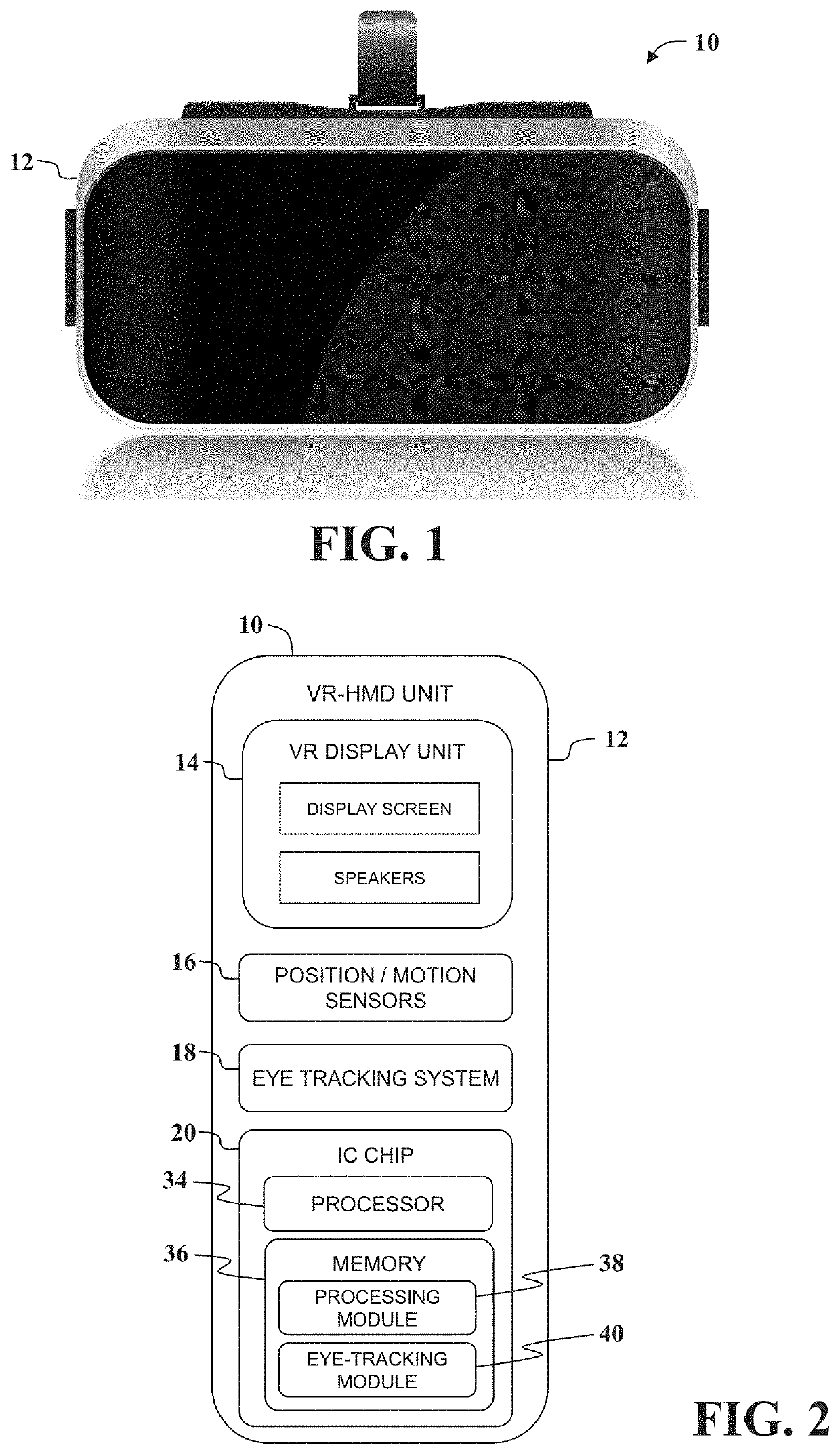
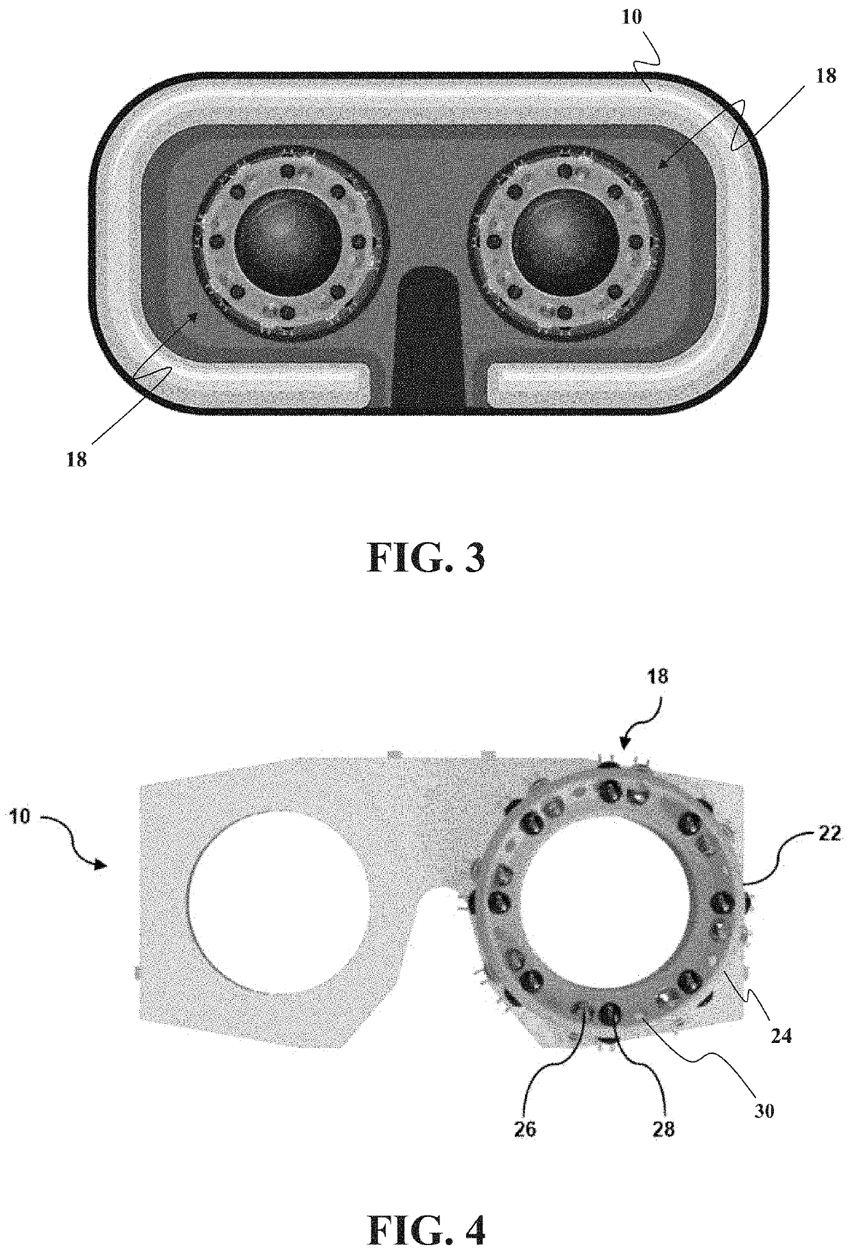
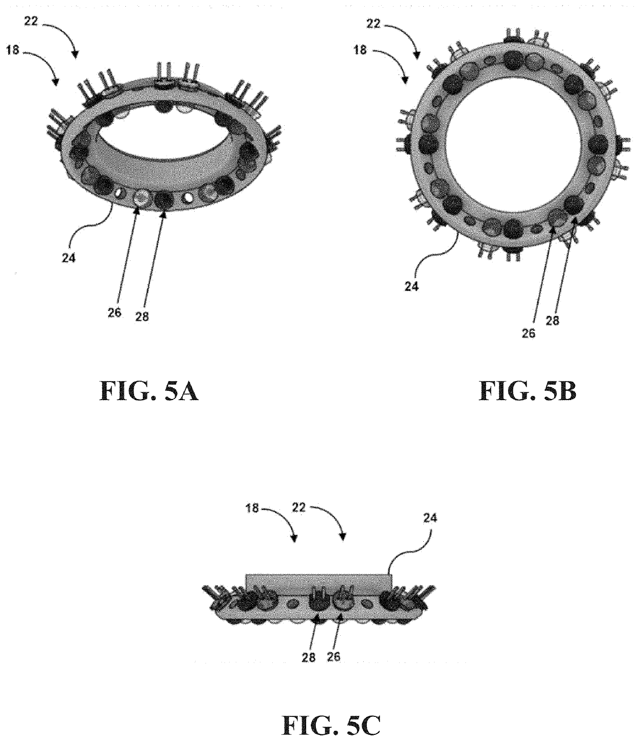
[0017]With reference to the drawings and in operation, the embodiments of the present invention provide a head-mounted display (HMD) unit and an eye tracking system for use with HMD units. The eye tracking system includes a number of photosensors and light emitters (e.g., NIR) placed at specific points, e.g., around a lens or see-through display placed in HMD (one eye tracking set per one eye). The light source illuminates the area of the eye in a variable mode, turning on and off specific diodes alternately, creating repetitive lighting patterns generated at high time frequency. This method improves data quality. Photosensors detect the intensity of light (e.g., NIR) reflected from the eye surface. Changing the eye alignment influence a change of light intensities registered on photosensors configured to monitor selected eye regions. Based on this rule, system calculates gaze direction. Variable temperature in HMD's interior can affect the photosensors readings, therefore additiona...


PUM


Abstract

An eye tracking system for use with a head-mounted display (HMD) unit is described. The eye tracking system includes a support frame mounted to the HMD unit, a light source mounted to the support frame and configured to illuminate an area of a patient eye, a plurality of photosensors mounted to the support frame and configured to receive reflected light from different portions of the illuminated patient eye, a temperature sensor mounted to the support frame and configured to measure a temperature of the photosensors, and a processor. The processor is programmed to execute an algorithm including a processing module that compensates photosensor measurement error due to variable operating temperature in the HMID unit, and an eye-tracking module that determines a gaze position of the patient eye using a mapping between intensities of photosensors and a gaze position estimated during a calibration procedure.

Description

CROSS-REFERENCE TO RELATED APPLICATION[0001]This application claims the benefit of U.S. Provisional Patent Application Ser. No. 63 / 064,078, filed Aug. 11, 2020, the disclosure of which is hereby incorporated by reference in its entirety.TECHNICAL FIELD[0002]The present invention relates to head-mounted display (HMD) units and, more specifically to a low-power eye tracking system for use in head-mounted display units.BACKGROUND OF THE INVENTION[0003]Nowadays, the most popular eye tracking products are based on IR cameras configured to record eye images. This data stream is used to determine the position of the pupil, which is then the basis for calculating the gaze vector. This approach offers high tracking accuracy and robustness against factors such as the shift of the headset. However, this solution is burdened with problems such as: 1) Complicated assembling, often using IR mirrors directing IR light reflected from the eyes onto the camera lens; 2) IR cameras are relatively expen...

Claims


Application Information

Patent Timeline
Patent Type & Authority Applications(United States)
IPC IPC(8): G06F3/01G01B11/00G01B11/14
CPCG06F3/013G01B11/14G01B11/002G02B27/0093G06F3/011G02B2027/0187
Inventor KRUKOWSKI, PIOTRMEINA, MICHALREDMERSKI, PIOTR
Owner INSEYE INC
Why Eureka
Try Eureka