Method of installing an anti-siphon assembly

a technology of anti-siphon device and installation assembly, which is applied in the directions of drawing-off water installation, machines/engines, packaging, etc., can solve the problem of difficult installation of anti-siphon device into the fuel filler neck of the fuel tank, and achieve the effect of facilitating installation of anti-siphon devi

Active Publication Date: 2012-12-06
KEEFER NEAL L +2
View PDF7 Cites 0 Cited by
  • Summary
  • Abstract
  • Description
  • Claims
  • Application Information

AI Technical Summary

Benefits of technology

[0006]It is an object of this invention to provide an anti-siphon installation assembly that facilitates installation of an anti-siphon device into a fuel filler neck of a fuel tank.SUMMARY OF THE INVENTION

Problems solved by technology

It may be difficult to install an anti-siphon device into a fuel filler neck of a fuel tank when the outer diameter of the anti-siphon device is smaller than the inner diameter of the fuel filler neck.

Method used


Image

  • Method of installing an anti-siphon assembly
  • Method of installing an anti-siphon assembly
  • Method of installing an anti-siphon assembly

Examples


Embodiment Construction

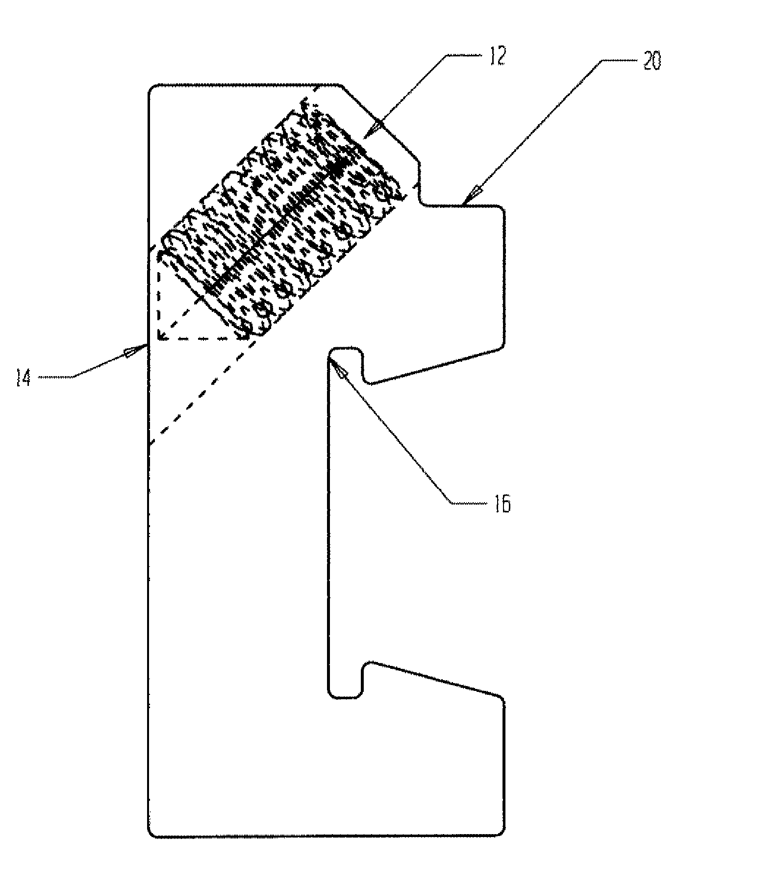
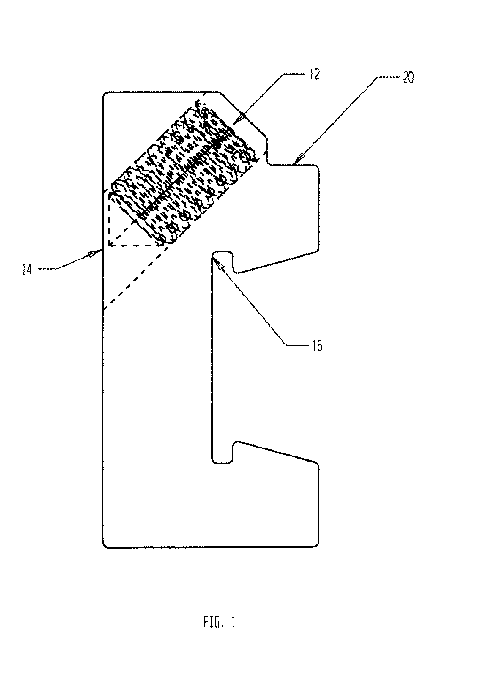
[0014]FIG. 1 is a side view of a retainer clip 10 with a set screw, such as a threaded cone point set screw 12, secured within and extending through an aperture, such as a threaded aperture 14. The cone point set screw 12 may include a point 16 at an end thereof such that point 16 may become slightly imbedded within, or may frictionally abut against, the interior wall 52 (FIG. 5) of a fuel filler neck when the set screw 12 is tightened within threaded aperture 14. In this manner, retainer clip 10 is secured within the fuel filler neck 38 (FIG. 5) of a fuel tank 54 (FIG. 5) in which the retainer clip 10 is installed.

[0015]Retainer clip 10 may include a recess 18 for mounting the retainer clip 10 on a spring 20 (FIG. 3). Retainer clip 10 may also include a stop surface 22, also called a support surface, for retaining the upper lip of an anti-siphon device (FIG. 5) thereon when the anti-siphon device is installed thereon. In one example embodiment, stop surface 22 may extend outwardly ...


PUM

PropertyMeasurementUnit
circular shapeaaaaaaaaaa
outer diameteraaaaaaaaaa
inner diameteraaaaaaaaaa

Abstract

An anti-siphon installation assembly includes a spring, a retainer clip mounted on the spring, the retainer clip including a support surface adapted to support an anti-siphon device thereon, and a locator clip mounted on the spring, the locator clip including an outwardly extending arm adapted to contact the upper surface of a fuel filler neck opening.

Description

[0001]This application claims the benefit of U.S. provisional patent application Ser. No. 61 / 206,503, filed on Jan. 30, 2009.BACKGROUND OF THE INVENTION[0002]1. Field of the Invention[0003]The present invention relates to an anti-siphon installation assembly, and in particular, to a fuel tank anti-siphon installation assembly that facilitates ease of installation of an anti-siphon assembly into a fuel filler neck of a fuel tank, so as to reduce the ability to siphon fuel through the fuel filler neck of the fuel tank.[0004]2. Background of the Invention[0005]It may be desirable to install an anti-siphon device in a fuel tank to reduce siphoning of fuel from the tank. It may be difficult to install an anti-siphon device into a fuel filler neck of a fuel tank when the outer diameter of the anti-siphon device is smaller than the inner diameter of the fuel filler neck. Accordingly, it may be desirable to provide an assembly for installation of an anti-siphon device into a fuel filler nec...

Claims


Application Information

Patent Timeline
Patent Type & Authority Applications(United States)
IPC IPC(8): B23P11/00
CPCY10T29/49947Y10T29/53652Y10T29/49872Y10T29/5363B60K15/0403Y10T137/0402Y10T137/3149
Inventor KEEFER, NEAL L.WATSON, KENNETH A.WAYMINE, EVAN
Owner KEEFER NEAL L
Why Eureka
Try Eureka