
Cable pulley

a cable and pulley technology, applied in the field of cable pulleys, can solve the problems of high weight of solid plastic pulleys and in particular pulleys made of steel, detriment of cable pulley stability, and undesirable complicated fabrication, so as to achieve the effect of reducing power loss or damag

Inactive Publication Date: 2012-12-06
LIEBHERR WERK NENZING
View PDF10 Cites 7 Cited by
  • Summary
  • Abstract
  • Description
  • Claims
  • Application Information

AI Technical Summary

Benefits of technology

[0033]By using light-weight components such as the cable pulley according to the present disclosure, energy savings are obtained in these machines during their operation and transport. Furthermore, light-weight machines can be used more universally. A weight saving of parts present on the boom in addition directly goes to the benefit of the payload. A particular advantage is obtained in that, due to the lower weight of the cable pulleys, which are attached to the boom, a longer boom can be erected and that in identically constructed machines longer booms can be used, without a larger counterweight being required.

Problems solved by technology

These known cable pulleys have, for example, the disadvantage that solid produced plastic pulleys and in particular pulleys made of steel have a high weight.
Material savings and the resulting savings in weight would be to the detriment of the stability of the cable pulley, which likewise is undesirable.
A complicated fabrication likewise is undesirable for reasons of cost.
The use of rigid materials such as fiber-reinforced plastics likewise is problematic here, since these materials are quickly damaged or destroyed by the rubbing contact with strongly tensioned steel cables.
This is important in particular because composite materials like fiber-reinforced plastics are relatively easily damaged by shocks, abrasion and the like.

Method used


Image

  • Cable pulley
  • Cable pulley
  • Cable pulley

Examples


Embodiment Construction

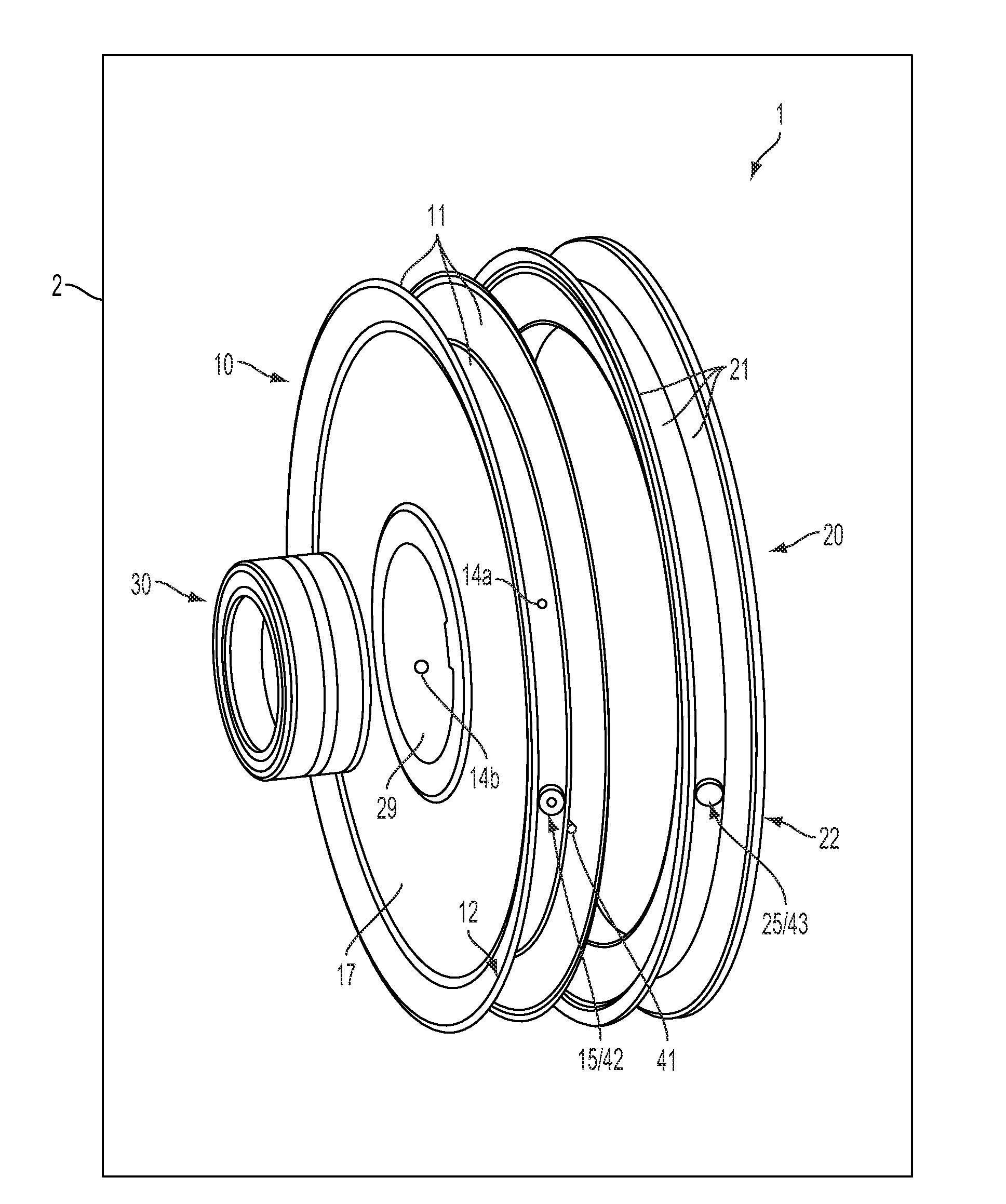
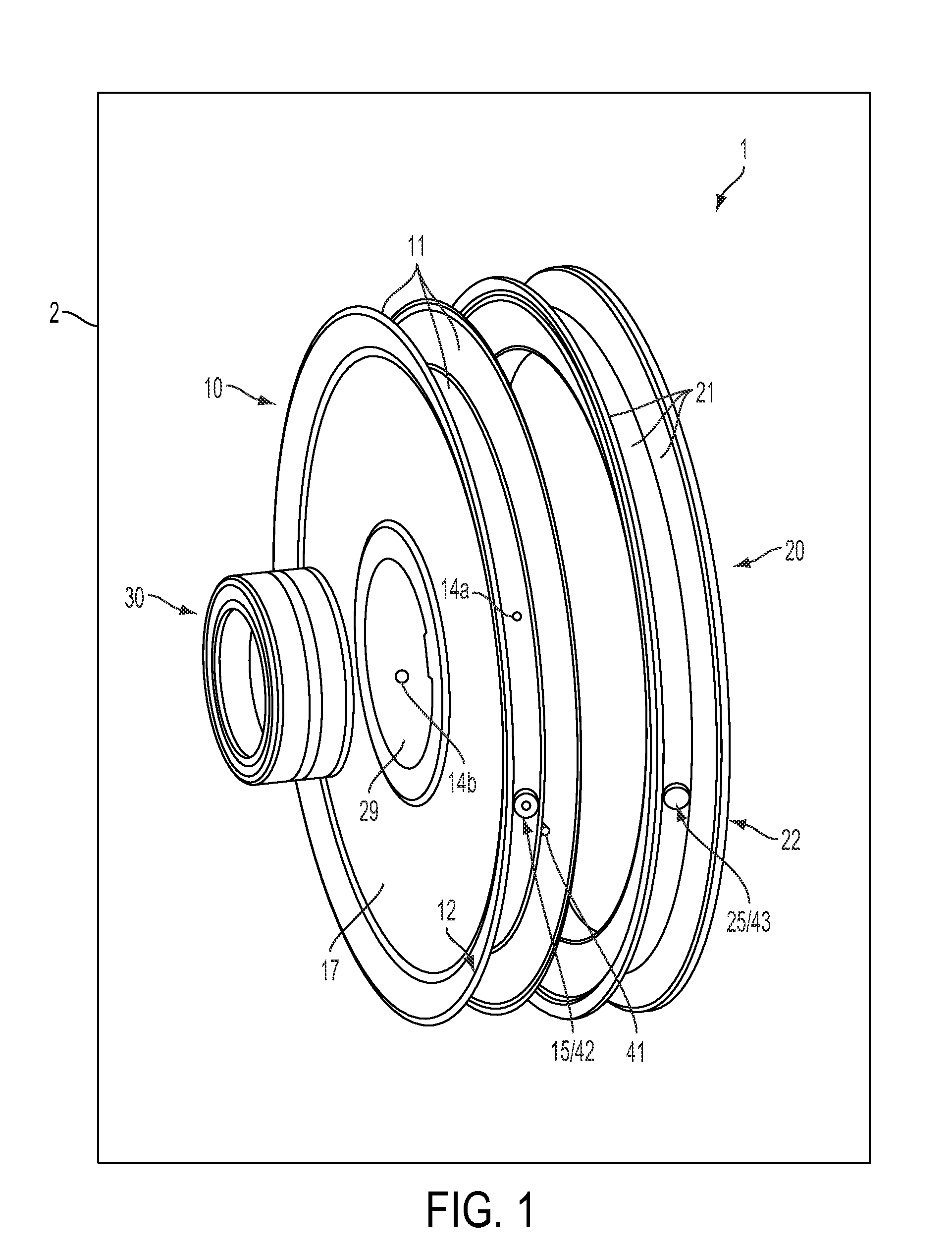
[0038]FIG. 1 shows an embodiment of a cable pulley 1 according to the present disclosure in an exploded representation.

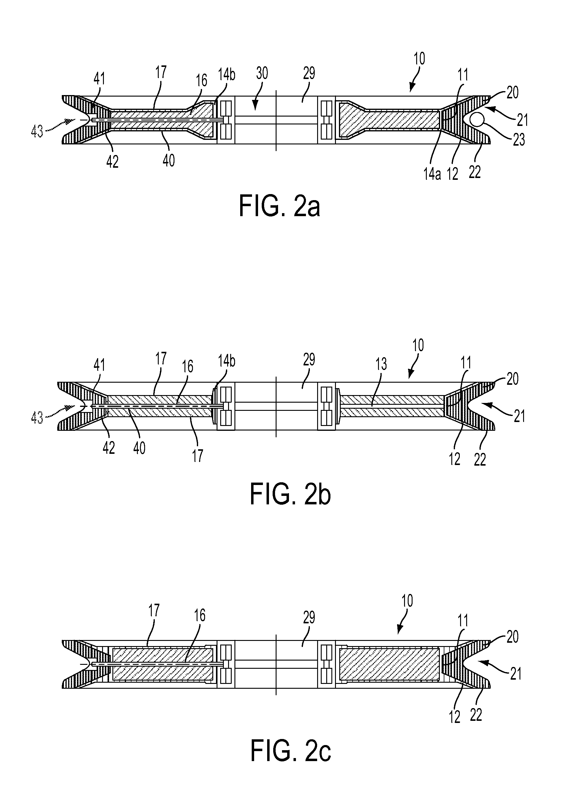
[0039]The cable pulley 1 includes a carrier body 10 as well as a groove body 20. The carrier body 10 has a wheel-shaped design, wherein a bore 29 is located in the center of the wheel on its axis of rotation. In this bore 29 a pivot bearing 30 is mounted.

[0040]The carrier body 10 is formed by two round disks 17 extending parallel to each other, an upper chord 14a and a lower chord 14b. The disks 17 extend from the bore 29 to the circumferential surface of the wheel and represent the lateral boundaries of the carrier body. Between the parallel disks 17 a core or spacer of various materials, for example a push core of a foamed plastic material or a similar rigid connection, can be mounted. Alternatively or in addition, another structure such as a hollow-chamber construction or a truss construction can be located in the space between the disks 17.

[0041]Along the two ed...


PUM


Abstract

The present disclosure relates to a cable pulley with a circumferentially extending groove for guiding a cable, wherein the cable pulley has a modular design and includes a wheel-shaped carrier body and a ring-shaped groove body, wherein the carrier body is at least partly made of a composite material, optionally a fiber-reinforced plastic material, and wherein the groove body circumferentially surrounds the carrier body and includes the groove.

Description

CROSS REFERENCE TO RELATED APPLICATIONS[0001]This application claims priority to German Patent Application No. 10 2011 102 801.7, entitled “Cable Pulley,” filed May 30, 2011, and German Patent Application No. 10 2011 108 230.5, entitled “Cable Pulley,” filed Jul. 21, 2011, which are hereby incorporated by reference in their entirety for all purposes.TECHNICAL FIELD[0002]This present disclosure relates to a cable pulley with a circumferentially extending groove for guiding a cable, the use of a cable pulley in a crane or an excavator, and a crane or an excavator with at least one cable pulley.BACKGROUND AND SUMMARY[0003]Cable pulleys have a wheel-shaped design and in their condition of use are rotatably mounted about their central axis. Along their circumference, they have a standardized groove with a groove base for guiding a cable. In the prior art, they are used to minimize power losses or damages during the deflection of the pull direction of cables. Applications of cable pulleys...

Claims


Application Information

Patent Timeline
IPC IPC(8): F16H55/48F16H55/40
CPCF16H55/48F16H57/0471F16H57/0464F16H55/50
Inventor RUEF, PATRICIASTREITZ, HOLGER
Owner LIEBHERR WERK NENZING
Learn More