Conversion of synchronous generator to synchronous condenser

a technology of synchronous generator and condenser, which is applied in the direction of electric generator control, dynamo-electric converter control, control system, etc., can solve the problem of time-consuming and laborious assembly of the starting motor to the rotor, and achieve the effect of facilitating the injection of excitation curren

Active Publication Date: 2012-12-06
GENERAL ELECTRIC CO
View PDF3 Cites 45 Cited by
  • Summary
  • Abstract
  • Description
  • Claims
  • Application Information

AI Technical Summary

Benefits of technology

[0003]In one aspect of the present invention, a synchronous condenser is provided. The synchronous condenser comprises a synchronous generator decoupled from a turbine. The generator has a rotor and a rotor shaft mounted within a stator. The rotor shaft has a first end decoupled from the turbine and a second end opposite the first end. A variable frequency drive, coupled to the generator, provides electrical energy to the stator to turn the rotor at a rotational speed that is proportional to a frequency of operation of the variable frequency drive. An exciter facilitates injection of excitation current into the generator rotor at any speed of rotation including standstill. A controller, operatively coupled to the variable frequency drive and the exciter, controls acceleration of the rotor to an operational speed enabling the generator to perform a synchronous condenser operation.

Problems solved by technology

Assembling the starting motor to the rotor can be time consuming.

Method used


Image

  • Conversion of synchronous generator to synchronous condenser
  • Conversion of synchronous generator to synchronous condenser
  • Conversion of synchronous generator to synchronous condenser

Examples


Embodiment Construction

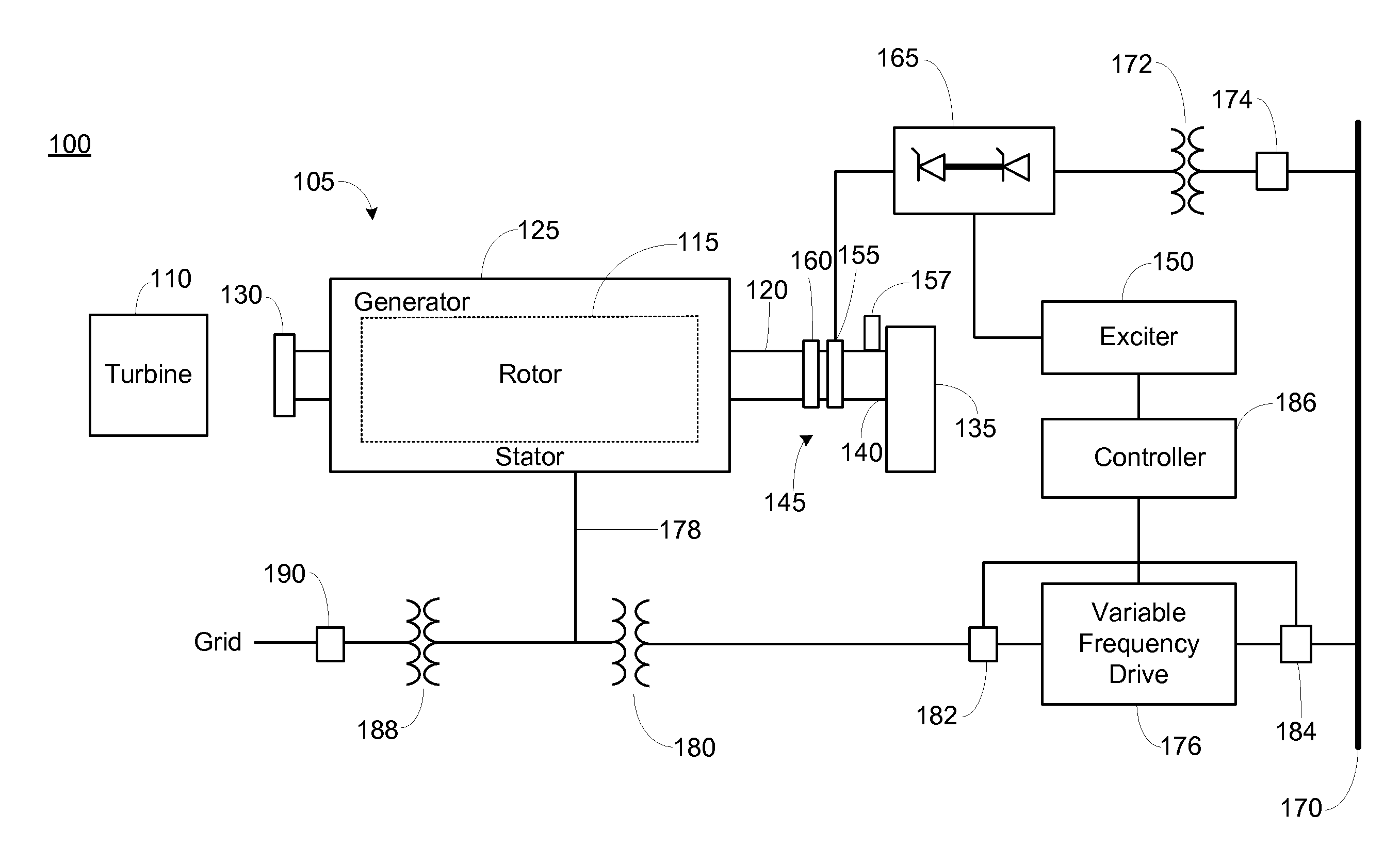
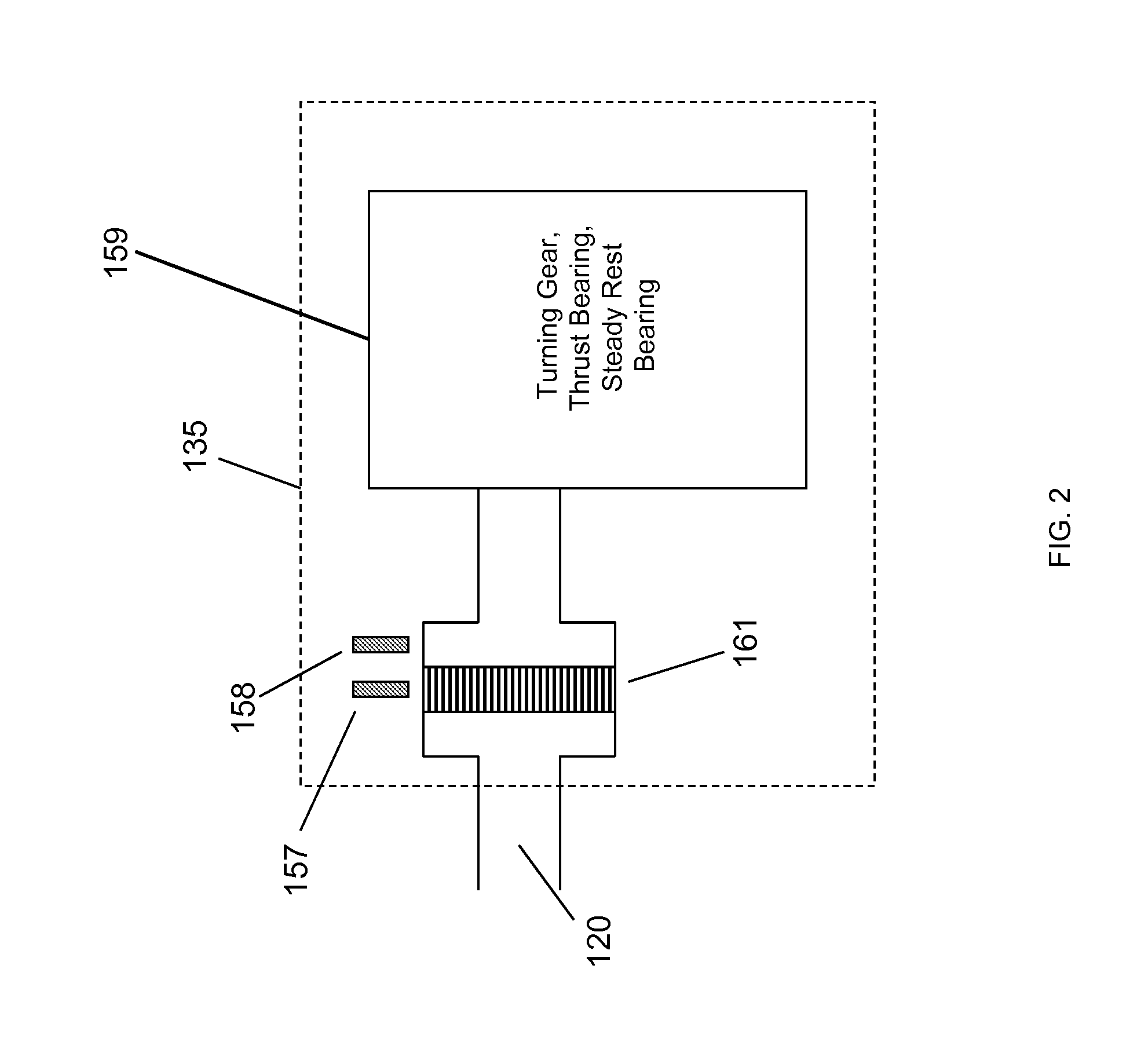
[0012]1 Overall Arrangement

[0013]Various embodiments of the present invention are directed to converting a synchronous generator driven by a steam turbine or a gas turbine to a synchronous condenser that can perform a synchronous condenser operation (i.e., generating reactive power or absorbing reactive power). In one embodiment, a generator decoupled from a turbine is used in conjunction with a variable frequency drive and an excitation system. The variable frequency drive provides electrical energy to the stator of the generator to turn the rotor at a rotational speed that is proportional to a frequency of operation of the variable frequency drive. In one embodiment, a transformer connects the variable frequency drive to the generator. The transformer may be a variable frequency drive output transformer or an auxiliary transformer. The excitation system injects an excitation current (e.g., direct current (DC)) into the rotor. A controller, operatively coupled to the variable frequ...


PUM


Abstract

An approach for converting a synchronous generator to a synchronous condenser is disclosed. In one aspect, a variable frequency driver is used to provide a starting power source to accelerate a synchronous generator decoupled from a turbine to an operational speed to act as a synchronous condenser. In another aspect, the synchronous condenser can be recoupled back to the turbine to form the synchronous generator.

Description

BACKGROUND OF THE INVENTION[0001]The present invention relates generally to synchronous machines and more particularly to converting a synchronous generator to a synchronous condenser.[0002]Synchronous generators driven by turbines are commonly used by power utilities to produce electrical energy. Often after many years of use, power utilities will retire or decommission synchronous generators from use as power generation units. In some cases, it is desirable to use these retired synchronous generators as synchronous condensers to generate reactive power or absorb reactive power. As a general proposition, a retired synchronous generator needs to be decoupled from the turbine that drove it when being used as a synchronous condenser. In order for the decoupled generator to be used as a synchronous condenser, it needs to be brought to operational speed. Typically, dedicated means such as a starting motor attached to the shaft of the rotor of the generator is used to bring the generator...

Claims


Application Information

Patent Timeline
Patent Type & Authority Applications(United States)
IPC IPC(8): H02P9/02
CPCH02P9/08
Inventor FOGARTY, JAMES MICHAELCUNNINGHAM, JOHN NOELGOTTUNG, GARY EDWARDSTUEBNER, DAVID MARK
Owner GENERAL ELECTRIC CO
Why Eureka
Try Eureka