Magnetic sensor and pattern for magnetic sensor
a magnetic sensor and sensor technology, applied in the direction of magnetic measurement, instruments, measurement devices, etc., can solve the problems of reducing the output amplitude of the whole magnetoresistive element circuit and unable to obtain sufficient magnetic field detection sensitivity, so as to prevent the effect of reducing the output amplitud
- Summary
- Abstract
- Description
- Claims
- Application Information
AI Technical Summary
Benefits of technology
Problems solved by technology
Method used
Image
Examples
first embodiment
Configuration of Magnetic Sensor
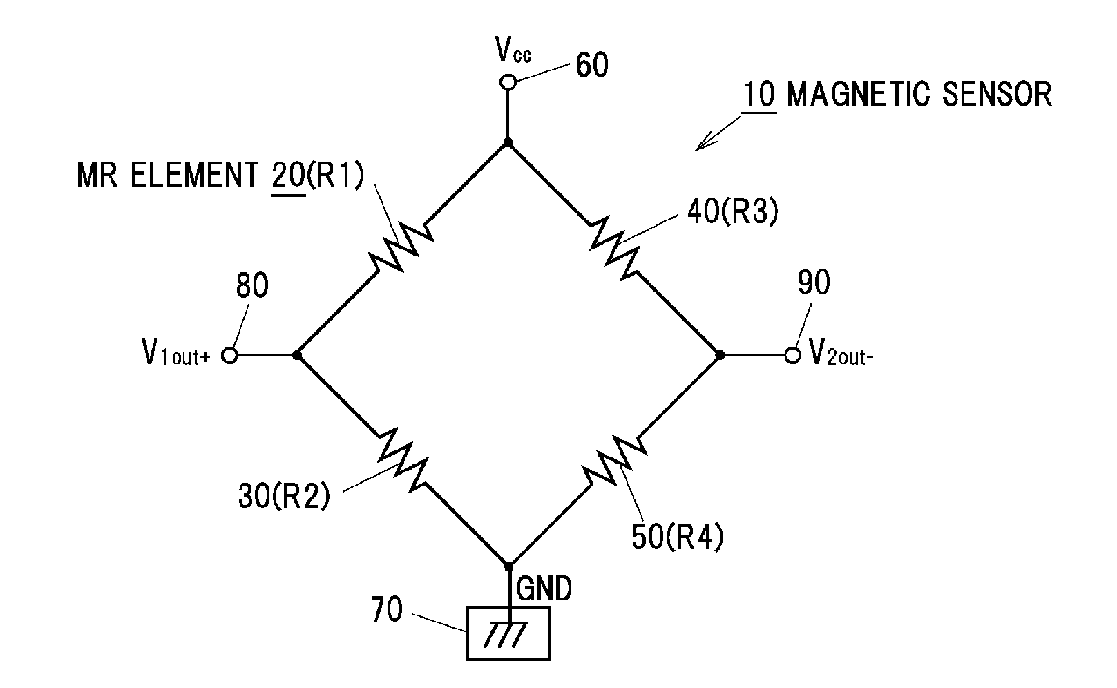
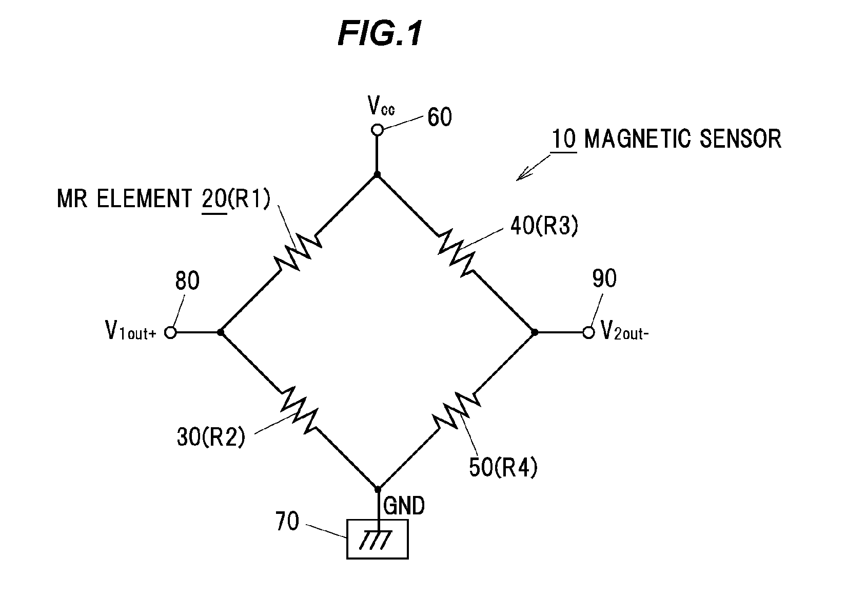
[0034]In FIG. 1, the whole magnetic sensor as one example is shown by a code 10. The magnetic sensor 10 includes an equivalent circuit (full bridge circuit) configured such that four MR elements (magnetoresistive elements) 20, 30, 40, 50 that are magnetic detection elements are connected to each other in a Wheatstone bridge shape.
[0035]As shown in FIG. 1, the four MR elements 20, 30, 40, 50 are configured to change electrical resistances R1 to R4 in accordance with directional change of magnetic field (directional change of magnetic flux) caused by a magnet to the magnetic sensor 10. As the magnetic detection element, for example, a Hall element and a magnetoimpedance effect element are included other than the MR element 20.
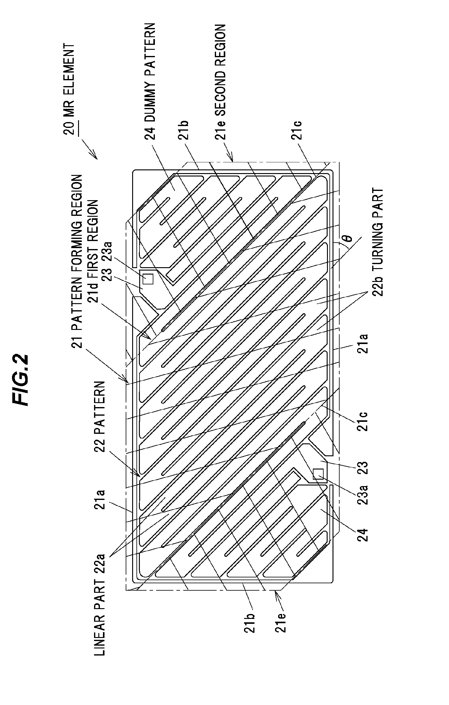
[0036]As shown in FIG. 1, the MR element 20 and the MR element 40 are connected to each other in series, and simultaneously the MR elements 30 and 50 are connected to each other in series. The MR elements 20, 40 and the MR elements...
second embodiment
[0062]Referring to FIG. 3, a main part of the MR element according to the second embodiment is shown. Similarly to the first embodiment, the basic configuration of the second embodiment is mainly characterized by the pattern forming region of the MR element 20. In FIG. 3, the substantially same elements as those in the first embodiment are indicated by the same names and numerals. Therefore, the detail explanation of the same elements will be omitted below.
[0063]The second embodiment is different from the first embodiment in the contour shape of the pattern forming region 21 of the MR element 20. As shown in FIG. 3, the contour shape of the pattern forming region 21 is formed to have a square shape in a plan view. The MR element 20 is formed to have a turning shape or meander shape that both end portions in the longitudinal direction of the patterns 22 arranged parallel to each other along the diagonal line of the square are alternately connected. The longitudinal direction of the p...
third embodiment
[0068]Referring to FIG. 4, a main part of the MR element according to the third embodiment is shown. Similarly to the first and second embodiments, the basic configuration of the third embodiment is mainly characterized by the pattern forming region of the MR element. The third embodiment is different from the first embodiment in the configuration of the MR element circuit and the contour shape of the pattern forming region. Further, in FIG. 4, the substantially same elements as those in the first and second embodiments are indicated by the same name and numerals. Therefore, the detail explanation of the same elements will be omitted below.
[0069]As shown in FIG. 4, the magnetic sensor 10 is composed of eight MR elements 20a to 50a, 20b to 50b that have the same structure and the same configuration. The MR elements 20a to 50a, 20b to 50b are arranged in a circular shape at phase difference of 45 degrees with a center focus on an intersection point O of the diagonal lines of octagon o...
PUM
 Abstract
Description
Claims
Application Information
 - R&D
- Intellectual Property
- Life Sciences
- Materials
- Tech Scout
- Unparalleled Data Quality
- Higher Quality Content
- 60% Fewer Hallucinations
Browse by: Latest US Patents, China's latest patents, Technical Efficacy Thesaurus, Application Domain, Technology Topic, Popular Technical Reports.
© 2025 PatSnap. All rights reserved.Legal|Privacy policy|Modern Slavery Act Transparency Statement|Sitemap|About US| Contact US: help@patsnap.com


