Radio communication apparatus and current reducing method

a technology of radio communication and current reduction, which is applied in the direction of substation equipment, antenna details, antennas, etc., can solve the problems of opening or closing the casing, and it is difficult to maintain the desired facing gap between the conductor piece and the folded fp

Inactive Publication Date: 2012-12-06
LENOVO INNOVATIONS LTD HONG KONG
View PDF2 Cites 251 Cited by
  • Summary
  • Abstract
  • Description
  • Claims
  • Application Information

AI Technical Summary

Benefits of technology

[0010]The present invention is devised in light of the above-mentioned circumstances and an object of the present invention is to provide a radio communication apparatus and a current reducing method capable of reducing a change in the antenna characteristics caused by the operations of opening and closing casings without deterioration in the operations of the opening and closing the casings.
[0014]According to the radio communication apparatus and the current reducing method of the present invention, the change in the antenna characteristics between the first and second states is suppressed without deterioration in the operations of opening and closing the casings.

Problems solved by technology

If the gap between the conductor piece and the FPC is small, it may cause a problem in an operation of opening or closing the casings.
In contrast, if the gap between the conductor piece and the FPC is large, it is difficult to maintain the desired facing gap between the conductor piece and the folded FPC.

Method used


Image

  • Radio communication apparatus and current reducing method
  • Radio communication apparatus and current reducing method
  • Radio communication apparatus and current reducing method

Examples


first embodiment

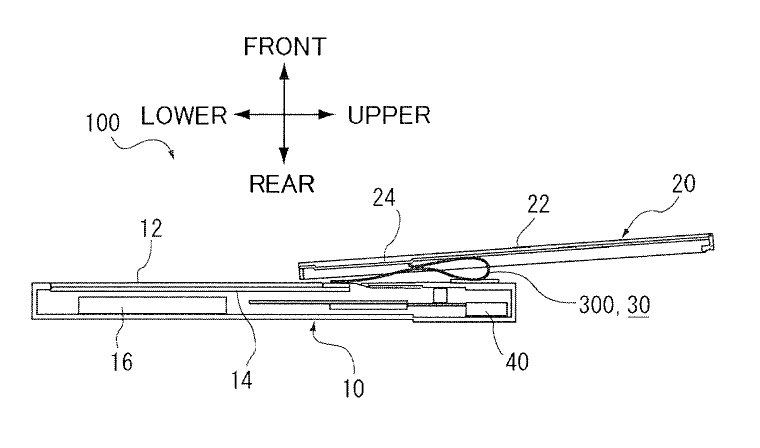
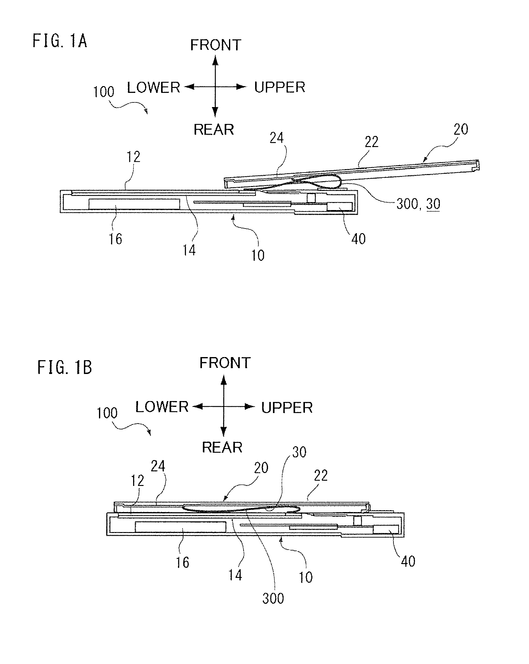
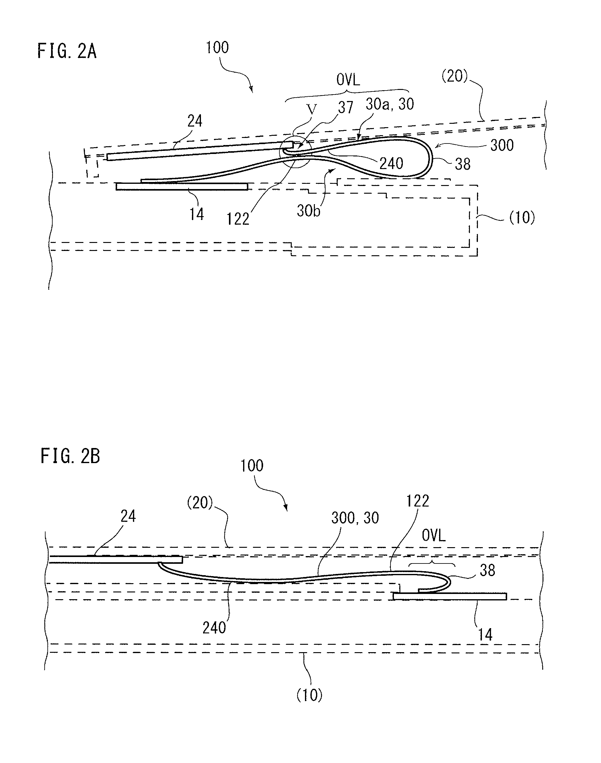
[0051]FIGS. 1A and 1B are longitudinal sectional views schematically illustrating a radio communication apparatus 100 of the embodiments of the present invention. FIG. 2A is a partial schematic view illustrating a first circuit substrate 14, a second circuit substrate 24, and an interconnect substrate 30 in an opened state of FIG. 1A. Likewise, FIG. 2B is a partial schematic view illustrating the first circuit substrate 14, the second circuit state 24, and the interconnect substrate 30 in a closed state of FIG. 1B. In FIGS. 2A and 2B, the first casing 10 and the second casing 20 are indicated by dashed lines and a part of their constituent elements are not illustrated for description.

[0052]First, the overview of the radio communication apparatus 100 will be described.

[0053]The radio communication apparatus 100 of this embodiment includes the first casing 10, the second casing 20, a connection section 300 that connects the first casing 10 to the second casing 20 to be movable, and an...

second embodiment

[0137]FIG. 10 is a partial schematic view illustrating a first circuit substrate 14, a second circuit substrate 24, and an interconnect substrate 30 in a radio communication apparatus 100 of a second embodiment. FIG. 10A shows an open state in which the second casing 20 is slid upward with respect to the first casing 10. FIG. 10B shows a closed state in which the second casing 20 is slid downward with respect to the first casing 10. The radio communication apparatus 100 of this embodiment is different from the radio communication apparatus shown in FIGS. 1 and 2 according to the first embodiment in that an overlapping region OVL of the interconnect substrate 30 in the opened state is greater than the overlapping region OVL of the interconnect substrate 30 in the closed state.

[0138]That is, in the radio communication apparatus 100 according to the present invention, the second state in which the interconnect substrate 30 is extended may be the opened state as in this embodiment (see ...

third embodiment

[0141]FIG. 11 is a sectional view illustrating the lamination of an interconnect substrate 30 of a third embodiment of the present invention. The interconnect substrate 30 of this embodiment is different from that according to the first embodiment (see FIG. 4) in that an adhesion layer 35c is interposed between a coat layer 35a and a conductor layer 34a.

[0142]One surface of the adhesion layer 35c (lower surface) is joined to the coat layer 35a. The front end of a connection portion 362 vertically drooping from the facing portion 361 is located at the same height as the other surface of the adhesion layer 35c (upper surface). In other words, the front end of the connection portion 362 is flush with the adhesion layer 35c. Further, the connection portion 362 is electrically connected to the conductor layer 34a by joining the adhesion layer 35c to the conductor layer 34a. Since the adhesion layer 35c slightly contracts over time in the surface-normal direction, the connection portion ...


PUM


Abstract

A radio communication apparatus includes: a first casing; a second casing; a connection section that connects the first and second casings to each other to be movable; and an antenna device that operates at a predetermined communication frequency. In the radio communication apparatus, first and second states are switched between by relatively moving the first and second casings. The first state is a state in which the first and second casings are opened or closed with respect to one another, and a first conductor (122) installed from the connection section to the first casing and a second conductor (240) installed from the connection section to the second casing are separated and faced each other. In the first state, the first conductor (122) and the second conductor (240) are electrically connected to each other at the communication frequency. The second state is a state in which the first and second casings are closed or opened with respect to one another.

Description

TECHNICAL FIELD[0001]The present invention relates to a radio communication apparatus and a current reducing method.BACKGROUND ART[0002]There are known cellular phones (radio communication apparatuses) that is opened and closed by relatively sliding or rotating their casings. In radio communication terminals, it is important to improve antenna characteristics. For example, Patent Document 1 discloses a case in which antenna characteristics deteriorate when a radio communication terminal approaches a human body, and a technology that prevents the antenna characteristics from deteriorating by providing a first parasitic element longer than the electrical length of an antenna on the front surface side of a casing including a display unit and a second parasitic element shorter than the electrical length of the antenna on the rear surface side of the casing.[0003]In cellular phones whose casings are opened and closed, a problem may arise in that the antenna characteristics of the cellula...

Claims


Application Information

Patent Timeline
Patent Type & Authority Applications(United States)
IPC IPC(8): H01Q1/24
CPCH01Q1/243H04M1/0214H01Q15/0086H04M1/0241H04M1/0235
Inventor SAKURAI, MASANORIKOBAYASHI, NAOKIANDO, NORIAKITOYAO, HIROSHIIMAZATO, MASAHARU
Owner LENOVO INNOVATIONS LTD HONG KONG
Why Eureka
Try Eureka