
Display device and driving method thereof

a display device and display panel technology, applied in the direction of instruments, computing, electric digital data processing, etc., can solve the problems of increasing the complexity of circuit design and increasing power consumption

Inactive Publication Date: 2012-12-06
AU OPTRONICS CORP
View PDF7 Cites 2 Cited by
  • Summary
  • Abstract
  • Description
  • Claims
  • Application Information

AI Technical Summary

Benefits of technology

[0023]In contrast to the prior art, the display device of the present invention utilizes an AC common voltage to drive the display panel. Therefore, the data driver of the present invention does not need to change the polarity of the display voltage, which further decreases the complexity for circuit design and reduces the power consumption.

Problems solved by technology

Such arrangement further increases the complexity for circuit design, and has more power consumption.

Method used


Image

  • Display device and driving method thereof
  • Display device and driving method thereof
  • Display device and driving method thereof

Examples


Embodiment Construction

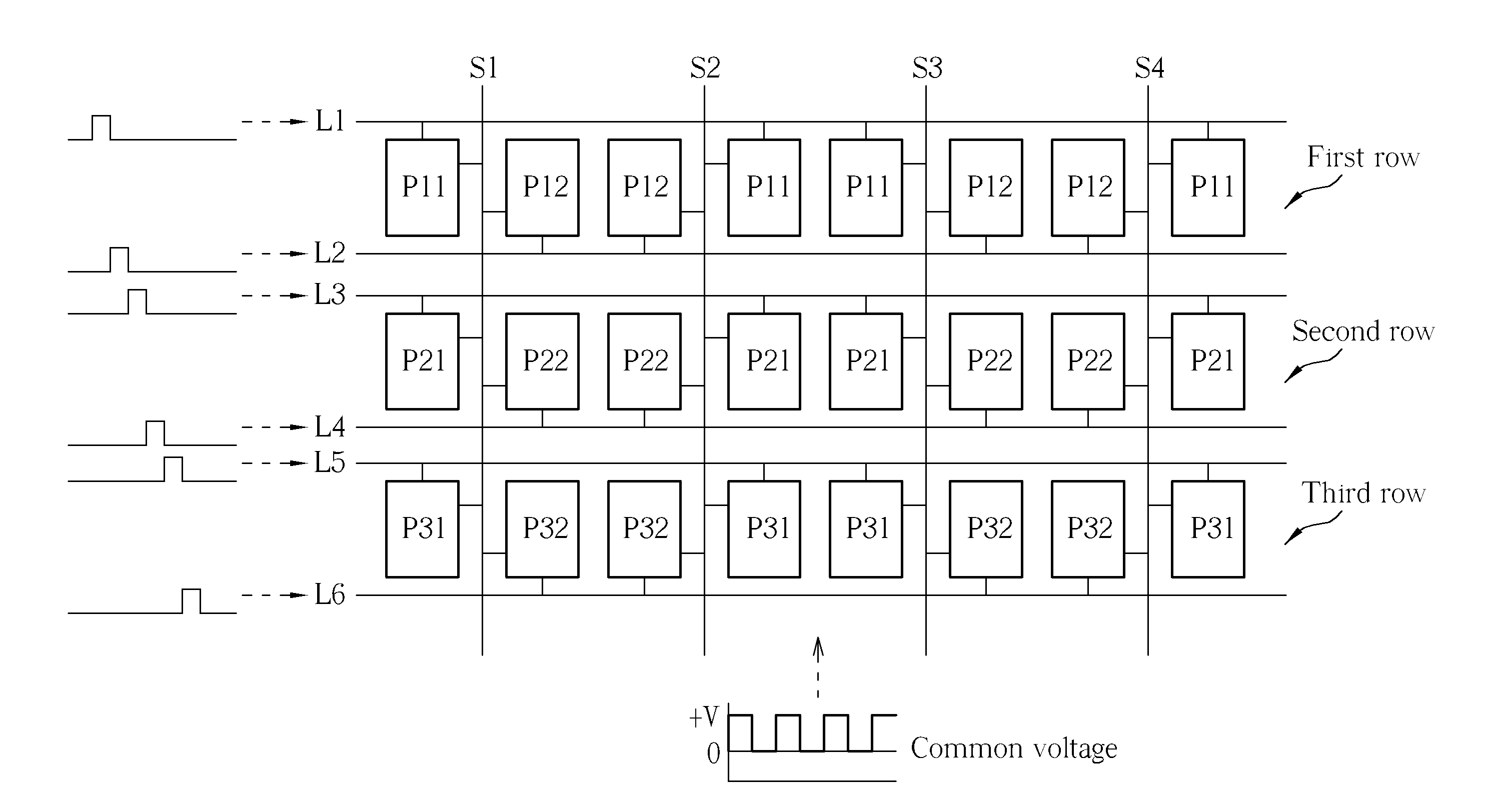
[0018]Please refer to FIG. 5. FIG. 5 is a diagram showing a display device 500 of the present invention. The display device 500 of the present invention comprises a display panel 110, a data driver 520, a scan driver 130, and a common voltage supply circuit 540. The display panel 110 comprises a plurality of pixels R, G, B arranged in a matrix form, a plurality of scan lines L, a plurality of data lines S, and a common electrode 112. The plurality of data lines S, the plurality of scan lines L, and the common electrode 112 are electrically connected to the plurality of pixels R, G, B, wherein two adjacent pixels are electrically connected to a same data line S. The data driver 520 is electrically connected to the plurality of data lines S for providing display voltages to the plurality of pixels R, G, B. The scan driver 130 is electrically connected to the plurality of scan lines L for turning on the pixels R, G, B in sequence via the scan line L. The common voltage supply circuit 5...


PUM


Abstract

A method for driving a display panel includes in a first time slot of a polarity inversion period turning on a plurality of first pixels in a first row via a first scan line, and providing a common voltage with a first potential; in a second time slot of the polarity inversion period turning on a plurality of second pixels in the first row via a second scan line, and providing the common voltage with a second potential; in a third time slot of the polarity inversion period turning on a plurality of first pixels in a second row via a third scan line, and providing the common voltage with the second potential; and in a fourth time slot of the polarity inversion period turning on a plurality of second pixels in the second row via a fourth scan line, and providing the common voltage with the first potential.

Description

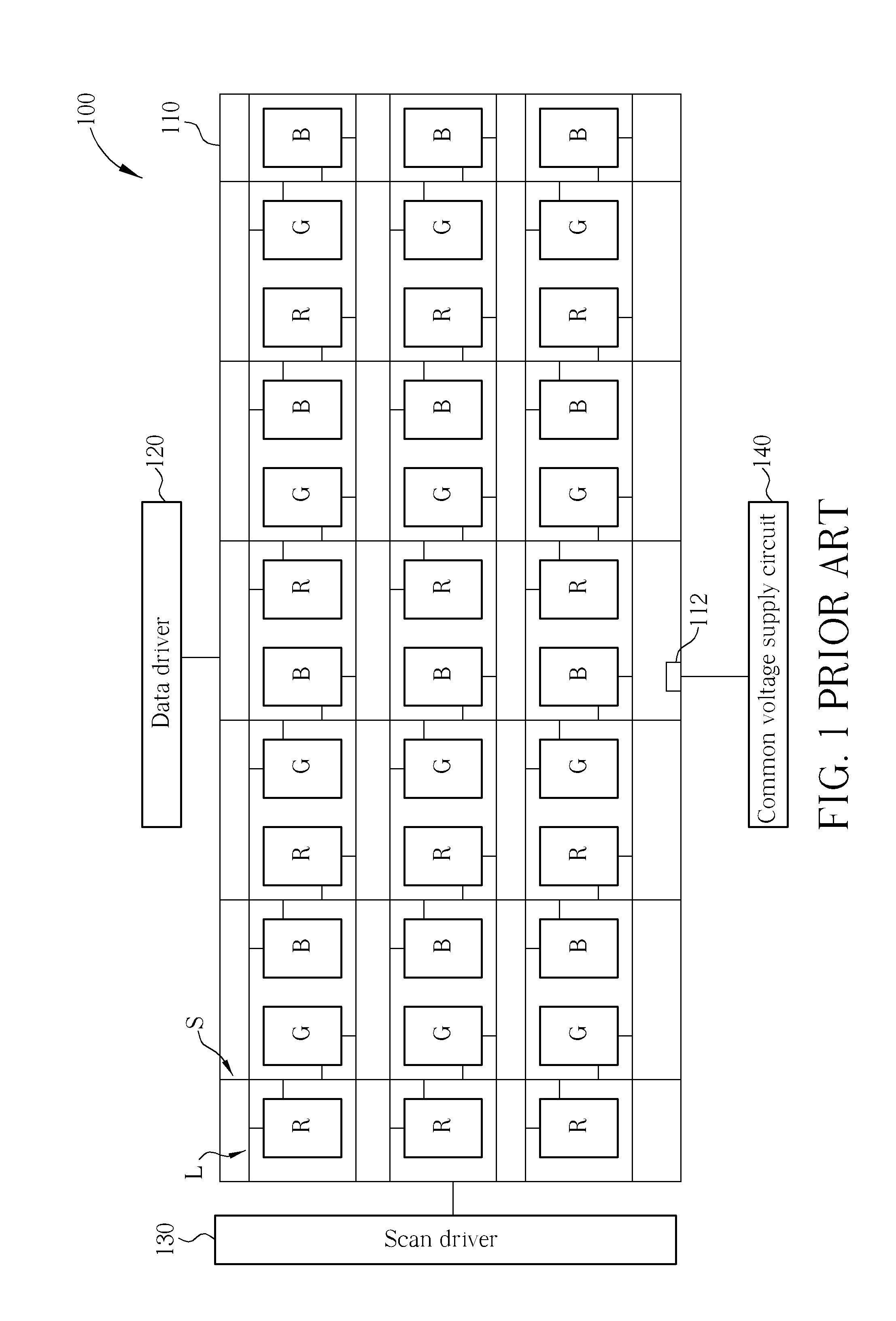
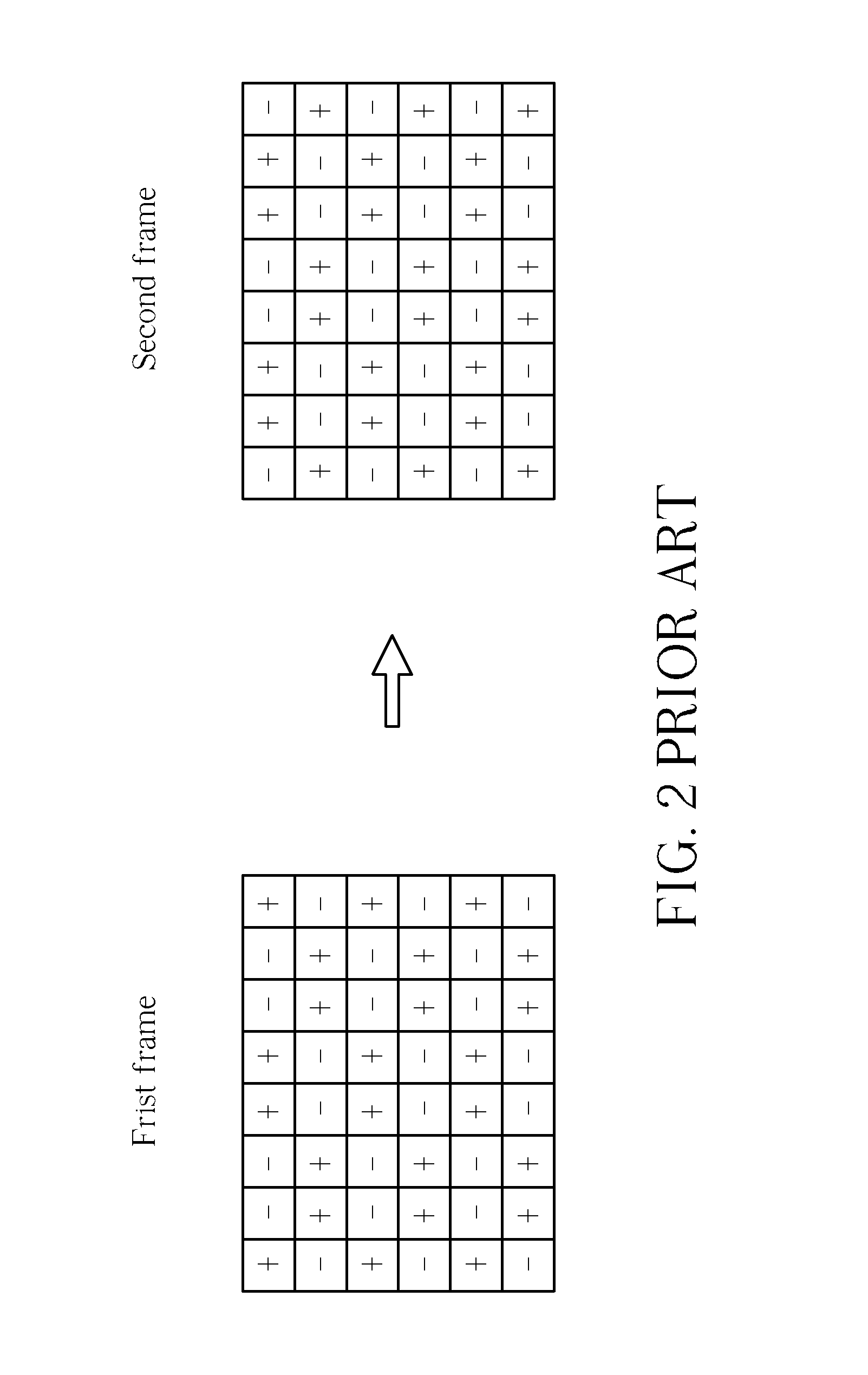
BACKGROUND OF THE INVENTION[0001]1. Field of the Invention[0002]The present invention relates to a method for driving a display panel, and more particularly, to a method for driving a display panel via an AC common voltage.[0003]2. Description of the Prior Art[0004]Please refer to FIG. 1. FIG. 1 is a diagram showing a display device 100 of the prior art. The display device 100 of the prior art comprises a display panel 110, a data driver 120, a scan driver 130, and a common voltage supply circuit 140. The display panel 100 comprises a plurality of pixels R, G, B arranged in a matrix form, a plurality of scan lines L, a plurality of data lines S, and a common electrode 112. The plurality of data lines S, the plurality of scan lines L, and the common electrode 112 are electrically connected to the plurality of pixels R, G, B, wherein two adjacent pixels are electrically connected to a same data line S. The data driver 120 is electrically connected to the plurality of data lines S for ...

Claims


Application Information

Patent Timeline
Patent Type & Authority Applications(United States)
IPC IPC(8): G06F3/038
CPCG09G3/3614G09G3/3648G09G2330/021G09G2300/0426G09G2320/0209G09G3/3655
Inventor LIN, YUN-CHUNGLI, CHUNG-LUNGTSAI, MENG-CHE
Owner AU OPTRONICS CORP
Learn More