
Fuse control system and method using defective mode detection

a control system and defective mode technology, applied in the direction of safety/protection circuits, cell component details, batteries, etc., can solve the problems of space increase, battery efficiency reduction, cost increase, etc., to reduce the design space of the fuse in the circuit design, improve the efficiency of the battery, and reduce the total circuit design cost

Active Publication Date: 2022-04-12
LG ENERGY SOLUTION LTD
View PDF34 Cites 0 Cited by
  • Summary
  • Abstract
  • Description
  • Claims
  • Application Information

AI Technical Summary

Benefits of technology

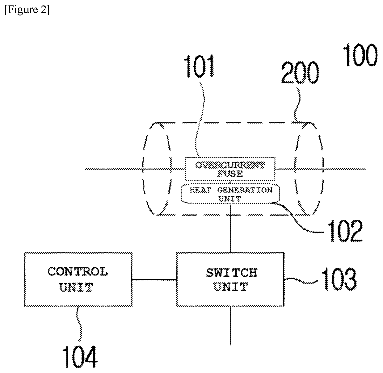
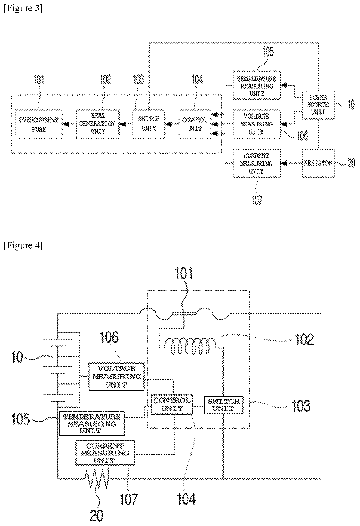
[0017]According to the embodiments of the present invention, in the fuse control system and method using the defective mode detection, a design in which a fusing mechanism of a signal fuse is integrated with a portion of the overcurrent fuse, which is to be melted, is made. Thus, a design space for the fuse in a circuit design is reduced, and thus there are advantages that it is possible to obtain an additional space, to reduce the total circuit design cost, and to improve efficiency of a battery by reducing circuit resistance.

Problems solved by technology

In this case, there are problems in that a design space increases, cost increases, and battery efficiency is reduced by increasing resistance, for examples.

Method used


Image

  • Fuse control system and method using defective mode detection
  • Fuse control system and method using defective mode detection
  • Fuse control system and method using defective mode detection

Examples


Embodiment Construction

[0023]Hereinafter, a preferred embodiment will be described for understanding the present invention. The following embodiment is just provided in order to make the present invention be understood easier, and thus the present invention is not limited by the embodiment.

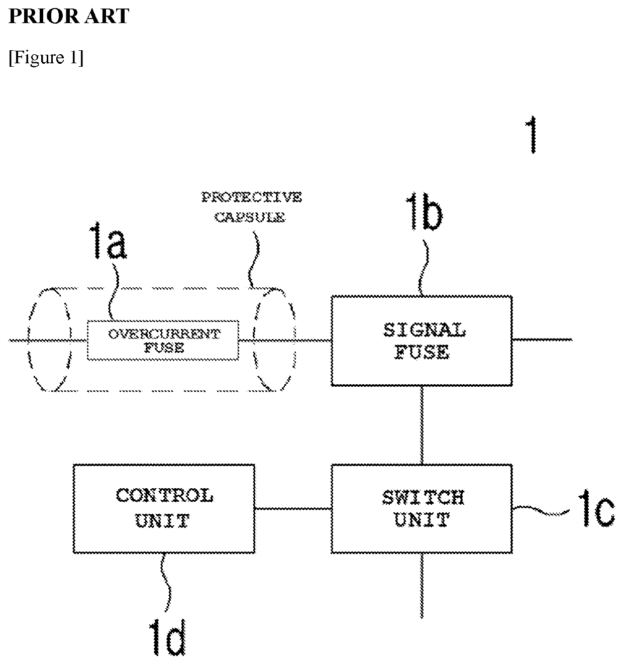
[0024]FIG. 1 is a diagram schematically illustrating a circuit (1) in the related art, in which an overcurrent fuse and a signal fuse are connected in series.

[0025]In FIG. 1, in the circuit (1) in the related art, in which an overcurrent fuse and a signal fuse are connected in series, an overcurrent fuse (1a) and a signal fuse (1b) are connected to each other in series, and the signal fuse (1b) is connected to a switch unit (1c) and a control unit (1d).

[0026]More specifically, in the circuit (1) in which the overcurrent fuse and the signal fuse are connected in series, the overcurrent fuse (1a) which is fused when a current having a value exceeding a threshold value allowed in the circuit is generated, and the signal fu...


PUM


Abstract

A fuse control system and method using a defective mode detection, in which an overcurrent protective fuse and a signal fuse capable of performing a function under various conditions in order to protect a circuit are integrated. Thus, it is possible to protect the circuit even in states such as overvoltage, a high temperature, a low temperature, and other dangerous states in addition to an overcurrent state and a short-circuited state. In addition, it is possible to reduce a wide design space and design cost which result from various kinds of fuses being used in series, and to simplify a circuit configuration. Consequently, since circuit resistance is reduced, it is possible to have a positive influence on a battery.

Description

CROSS-REFERENCE TO RELATED APPLICATIONS[0001]The present application is a national phase entry under 35 U.S.C. § 371 of International Application No. PCT / KR2019 / 009708 filed Aug. 5, 2019, published in Korean, which claims priority from Korean Patent Application No. 10-2018-0103915 filed Aug. 31, 2018, all of which are incorporated herein by reference.TECHNICAL FIELD[0002]This application claims priority to and the benefit of Korean Patent Application No. 10-2018-0103915 filed in the Korean Intellectual Property Office on Aug. 31, 2018, the entire contents of which are incorporated herein by reference.[0003]The present invention relates to a fuse control system and method using a defective mode detection, and more particularly, to a fuse control system and method using a defective mode detection, in which an overcurrent protective fuse and a signal fuse are integrated, and thus it is possible to increase utilization of a space in a circuit design, to reduce design cost, and to improv...

Claims


Application Information

Patent Timeline
Patent Type & Authority Patents(United States)
IPC IPC(8): H01H85/00H02H3/02H02H5/04H02H3/10H02H3/38
CPCH01H85/0047H02H3/021H02H3/10H02H5/041H02H3/38H02H7/18H02H3/20H01H37/76H02H3/087H01M50/583H01M2200/103H02J7/00304Y02E60/10
Inventor LEE, JAE CHAN
Owner LG ENERGY SOLUTION LTD
Learn More