

Power supply apparatus and power supply method
a power supply apparatus and power supply technology, applied in the direction of dc motor rotation control, feed-through capacitors, engine starters, etc., can solve the problems of short service time device bulkiness, and short service life of batteries for delivering such high currents, etc., to achieve high charge and discharge efficiency, long life, and high power density of supercapacitors
- Summary
- Abstract
- Description
- Claims
- Application Information
AI Technical Summary
Benefits of technology
Problems solved by technology
Method used
Image

Examples
first embodiment
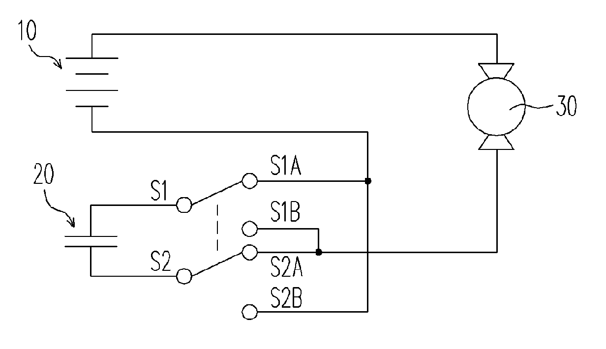
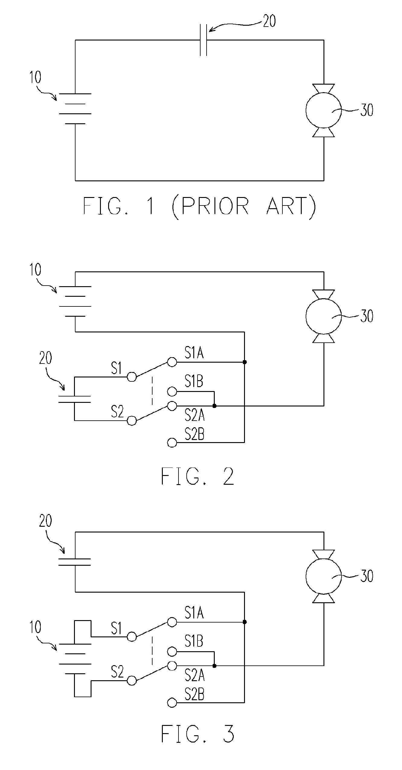
[0034]FIG. 2 illustrates the first embodiment of this invention wherein the polarity connection of the supercapacitor 20 to the battery 10 is controlled by a double-pole, double-throw (DPDT) controller consisting of two switches. With DPDT at the state of S1-S1A and S2-S2A as shown in FIG. 2, the supercapacitor 20 will be charged by the battery 10 at the same time while the load 30 is driven by the battery 10. Even under the situation that the voltage of the battery 10 is insufficient to drive the load 30, a charging current can still pass the load 30 to charge the supercapacitor 20. The flow path of charging current is as follows: the positive pole (longer bar) of the battery 10, the load 30, S2A, S2, the supercapacitor 20, S1, S1A, and then the negative pole (shorter bar) of the battery 10. As soon as the supercapacitor 20 is charged to the potential of the battery 10, the charging current stops flowing and the load 30 will be stalled.
[0035] Subsequently, by switching the DPDT to...
second embodiment
[0043]FIG. 3 shows the second embodiment of the present invention on using the reciprocating switches for a load 30 moving bi-directionally, for example, a garage door, an electric curtain or an elevator. With the DPDT is set at the state as shown in FIG. 3, the battery 10 provides a current that flows as follows: the positive pole (longer bar) of the battery 10, S1, S1A, the supercapacitor 20, the load 30, S2A, S2 and the negative pole (shorter bar) of the battery 10. The current may drive the load 30, but will definitely charge the supercapacitor 20 so long as the supercapacitor 20 has a lower potential than the battery 10. When the supercapacitor 20 is charged to the negative potential of the battery 10, the current flow will cease and the load 30 will be stalled.
[0044] Alternatively, the discharging of the battery 10 can be synchronized with the movements of the load 30, that is, the battery 10 terminates discharging when the load 30 stops. In the case that the driving force of...
third embodiment
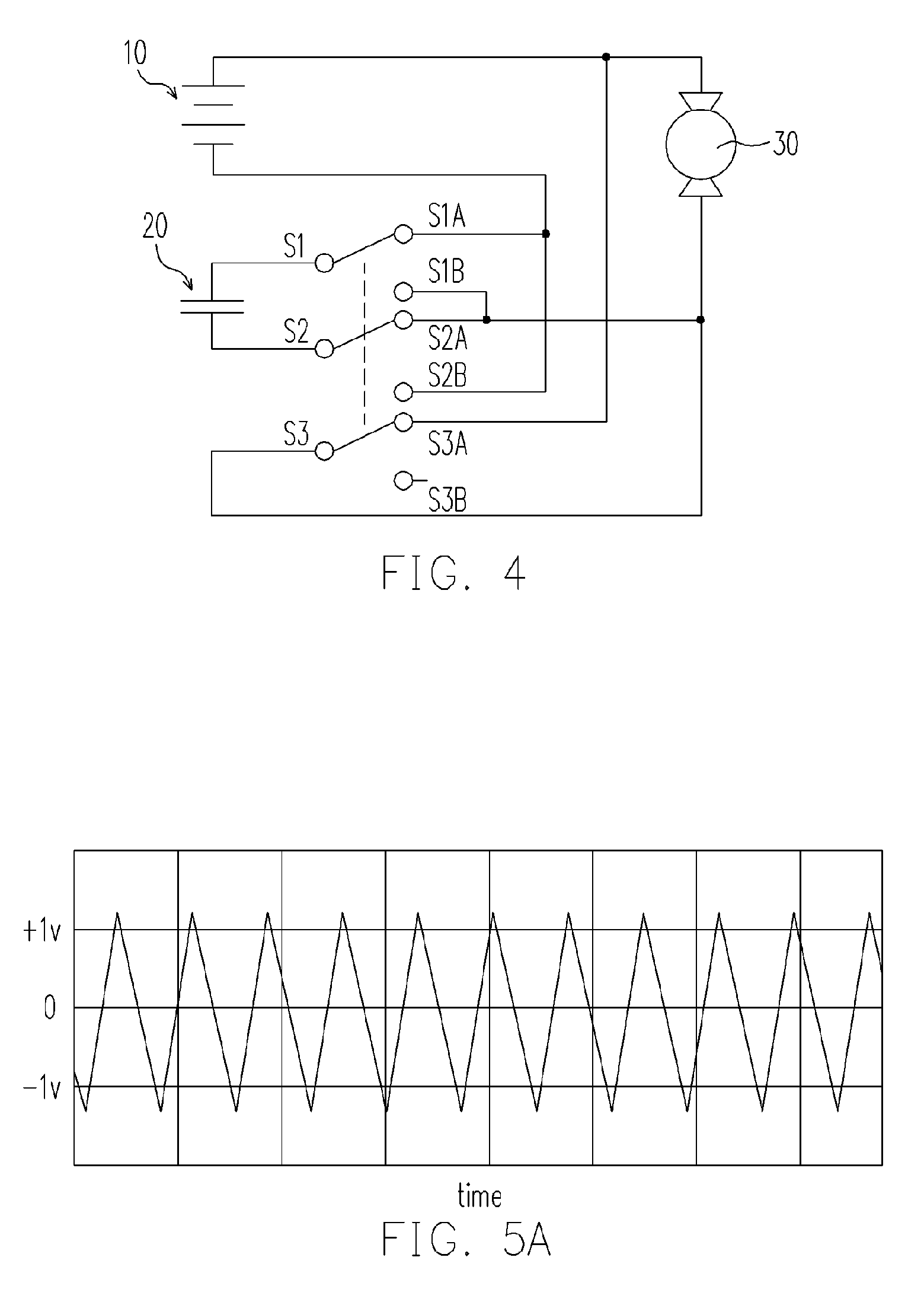
[0047]FIG. 4 shows the third embodiment of the present invention wherein the battery 10 quickly charges the supercapacitor 20 without passing the load 30. A trigger with three pole double throw (TPDT) consisting of three switches, wherein S1, S2 and S3 are common contacts, is employed for reversing the polarity connection between the supercapacitor 20 and the battery 10. As the TPDT is at the normally closed state (S1-S1A, S2-S2A and S3-S3A) as shown in FIG. 4, the battery 10 will charge the supercapacitor 20 by the following route: the positive pole (longer bar) of the battery 10, S3A, S3, S2A, S2, the supercapacitor 20, S1, S1A and the negative pole (shorter bar) of the battery 10. A push-latching button (not shown) can be used to initiate the charging of the supercapacitor 20.
[0048] Since the charging current does not flow through the load 30, the load 30 is stationary. Moreover, as the battery 10 and the supercapacitor 20 are essentially in an electric-short state, the battery ...
PUM
 Abstract
Description
Claims
Application Information