Method, device and system for indicating user equipment-specific demodulation reference signal
- Summary
- Abstract
- Description
- Claims
- Application Information
AI Technical Summary
Benefits of technology
Problems solved by technology
Method used
Image
Examples
first embodiment
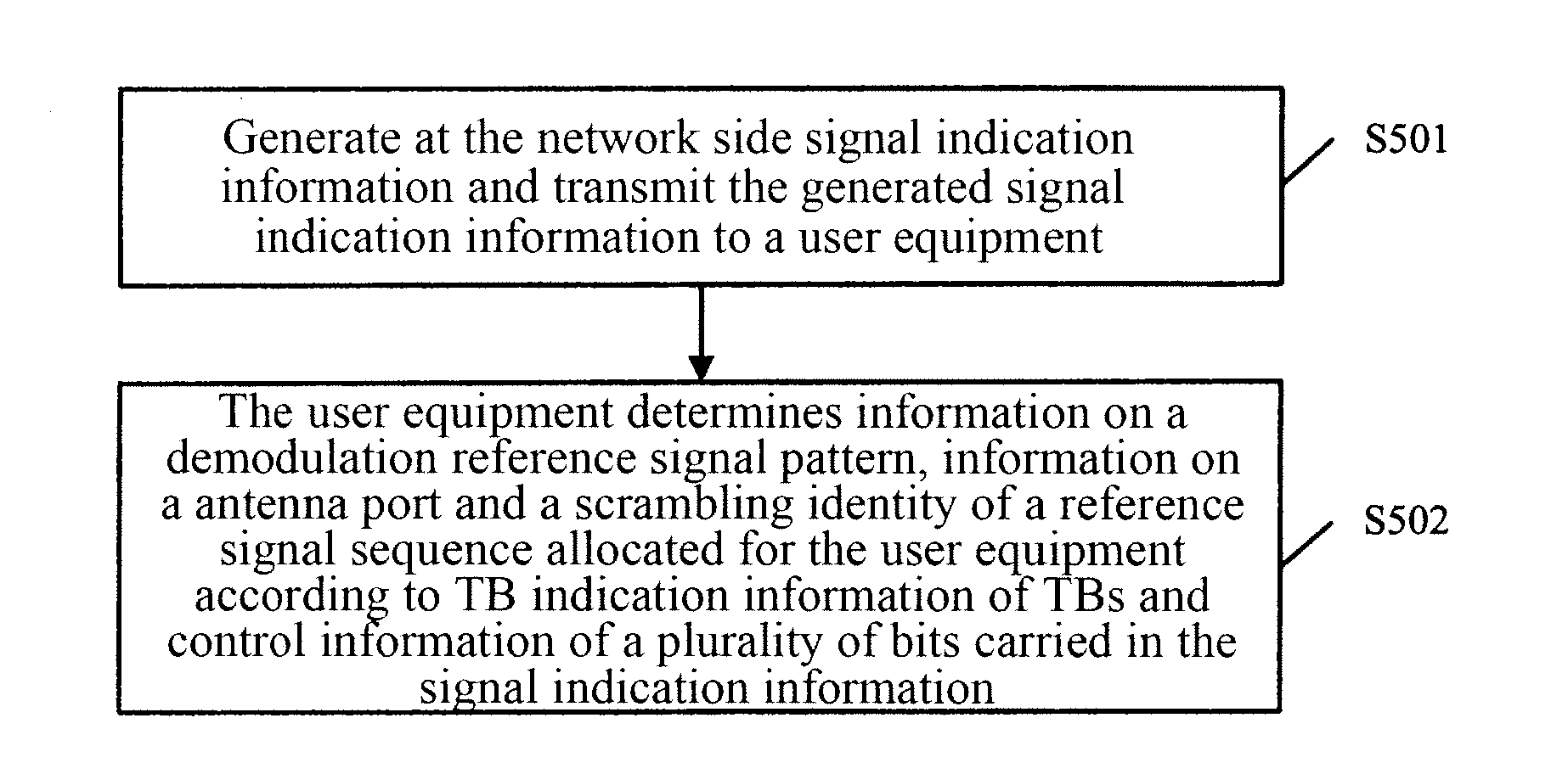
[0038]The first embodiment of the invention provides a method for indicating a user equipment-specific demodulation reference signal, which as illustrated in FIG. 6 includes:
[0039]Step S601. Signal indication information is generated at the network side, and the generated signal indication information is transmitted to a user equipment.
[0040]Step S602. The user equipment determines a demodulation reference signal pattern which is one of the Rank-2 pattern, the first Rank-4 pattern and the Rank-8 pattern, an antenna port and a scrambling identity of a reference signal sequence which is one of two scrambling identities, allocated for the user equipment according to TB indication information corresponding respectively to two TBs and 3-bit control information carried in the received signal indication information.
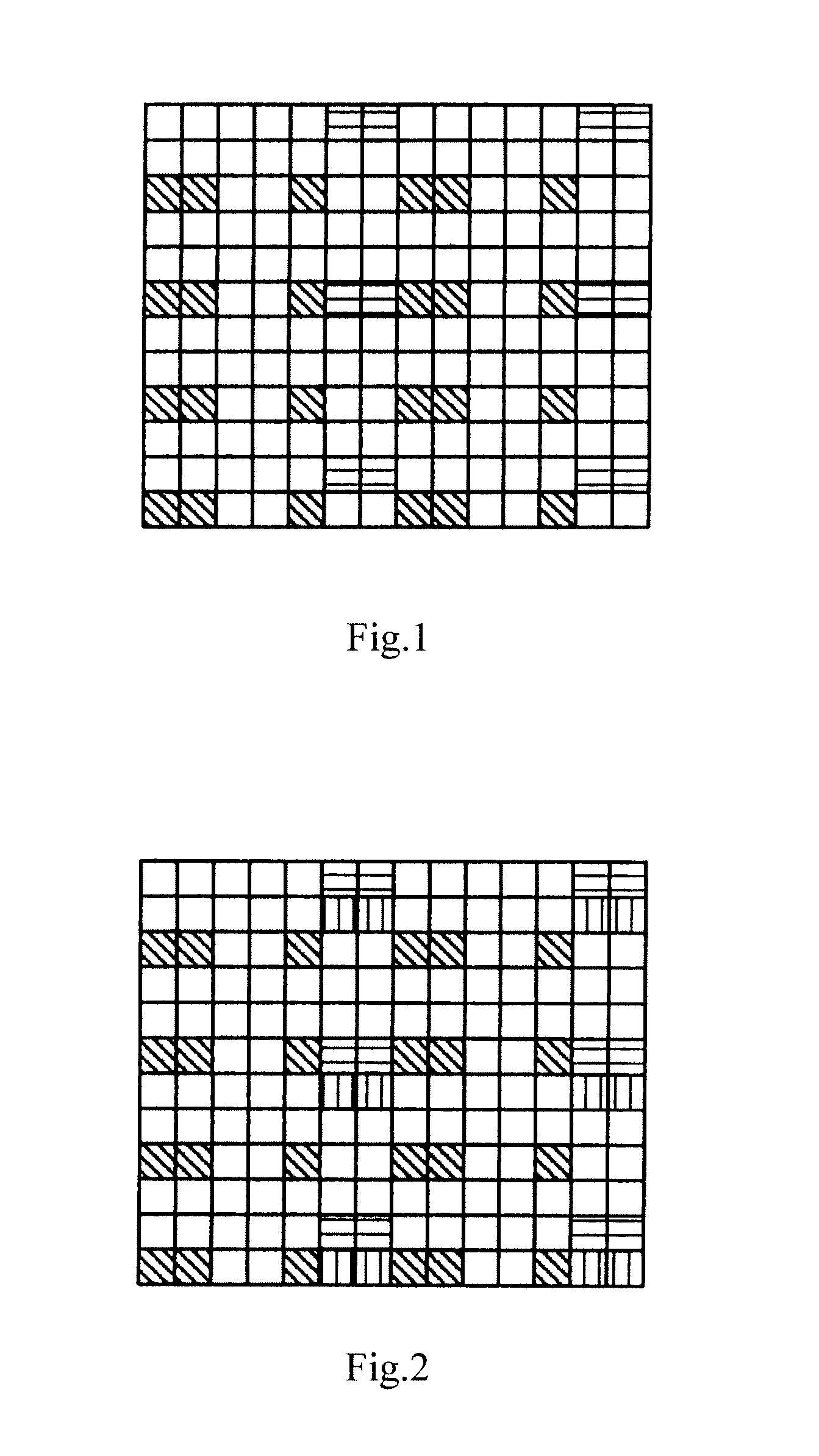
[0041]Particularly the Rank-2 pattern is a pattern for allocation of one or two antenna ports, the first Rank-4 pattern is a pattern for allocation of three or four antenna port...
second embodiment
[0082]The second embodiment of the invention further provides a method for indicating a user equipment-specific demodulation reference signal, which as illustrated in FIG. 7 includes:
[0083]Step S701. Signal indication information is generated at the network side, and the generated signal indication information is transmitted to a user equipment.
[0084]Step S702. The user equipment determines a demodulation reference signal pattern which is one of the Rank-2 pattern, the first Rank-4 pattern, the second Rank-4 pattern and the Rank-8 pattern, an antenna port and a scrambling identity of a reference signal sequence which is one of two scrambling identities, allocated for the user equipment according to TB indication information corresponding respectively to two TBs and 3-bit control information carried in the received signal indication information.
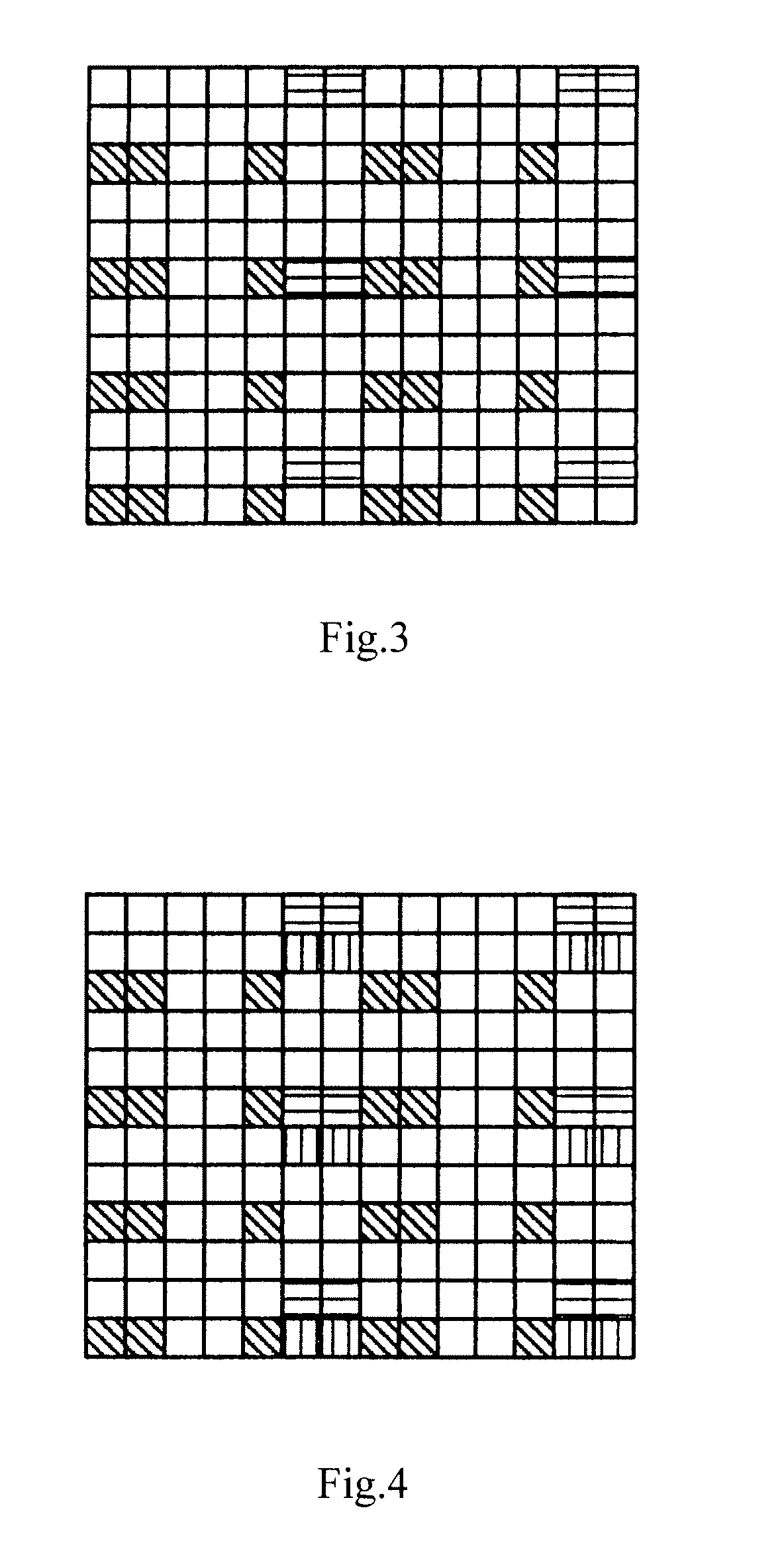
[0085]Particularly the Rank-2 pattern is a pattern for allocation of one or two antenna ports, the first Rank-4 pattern is a pattern for allo...
third embodiment
[0104]In the foregoing second embodiment, only one of the combination of the status 5 and the status 6 and the combination of the status 23 and the status 24 can be selected, and in Rank to indicate all of the status 5, the status 6, the status 23 and the status 24, the present third embodiment further provides a method for indicating a user equipment-specific demodulation reference signal, which as illustrated in FIG. 8 includes:
[0105]Step S801. Signal indication information is generated at the network side, and the generated signal indication information is transmitted to a user equipment.
[0106]Step S802. The user equipment determines a demodulation reference signal pattern which is one of the Rank-2 pattern, the first Rank-4 pattern, the second Rank-4 pattern and the Rank-8 pattern, an antenna port and a scrambling identity of a reference signal sequence which is one of two scrambling identities, allocated for the user equipment according to TB indication information correspondin...
PUM
 Abstract
Description
Claims
Application Information
 - R&D
- Intellectual Property
- Life Sciences
- Materials
- Tech Scout
- Unparalleled Data Quality
- Higher Quality Content
- 60% Fewer Hallucinations
Browse by: Latest US Patents, China's latest patents, Technical Efficacy Thesaurus, Application Domain, Technology Topic, Popular Technical Reports.
© 2025 PatSnap. All rights reserved.Legal|Privacy policy|Modern Slavery Act Transparency Statement|Sitemap|About US| Contact US: help@patsnap.com


