Decoder with dynamic range compensation

a dynamic range compensation and encoder technology, applied in signal generators with optical-mechanical scanning, color television with bandwidth reduction, etc., can solve the problems of increasing memory bandwidth requirements, increasing desire for increased higher fidelity, and encoding and/or decoding speeds

Inactive Publication Date: 2012-12-06
SHARP KK
View PDF12 Cites 6 Cited by
  • Summary
  • Abstract
  • Description
  • Claims
  • Application Information

AI Technical Summary

Problems solved by technology

As the computational complexity increases, the encoding and/or decoding speeds tend to decrease.
Also, the desire for increased higher fidelity tends to increase over time which tends to require increasingly larger memory requirements, increasingly larger memory bandwidth requirements, and increasing hardware complexity.
The increasing memory requirements and the increas

Method used


Image

  • Decoder with dynamic range compensation
  • Decoder with dynamic range compensation
  • Decoder with dynamic range compensation

Examples


Embodiment Construction

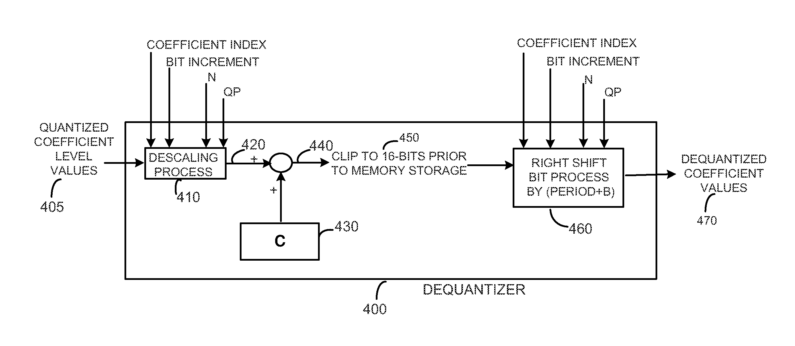
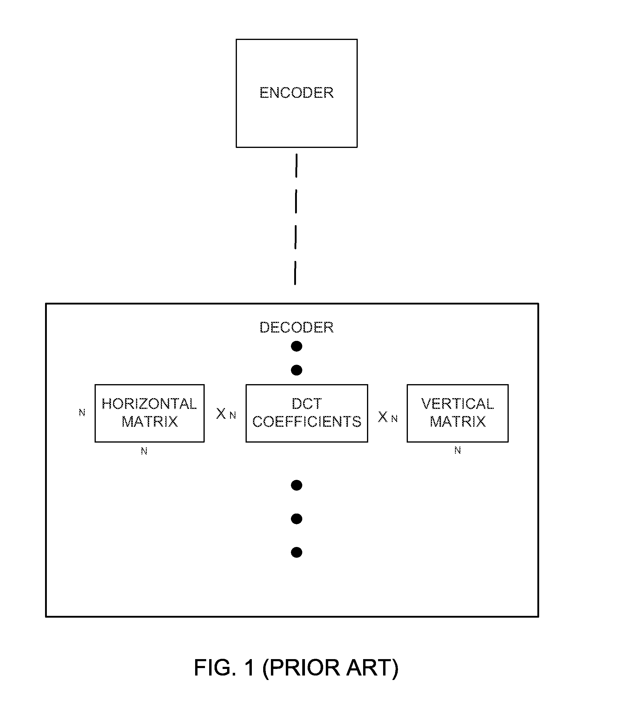
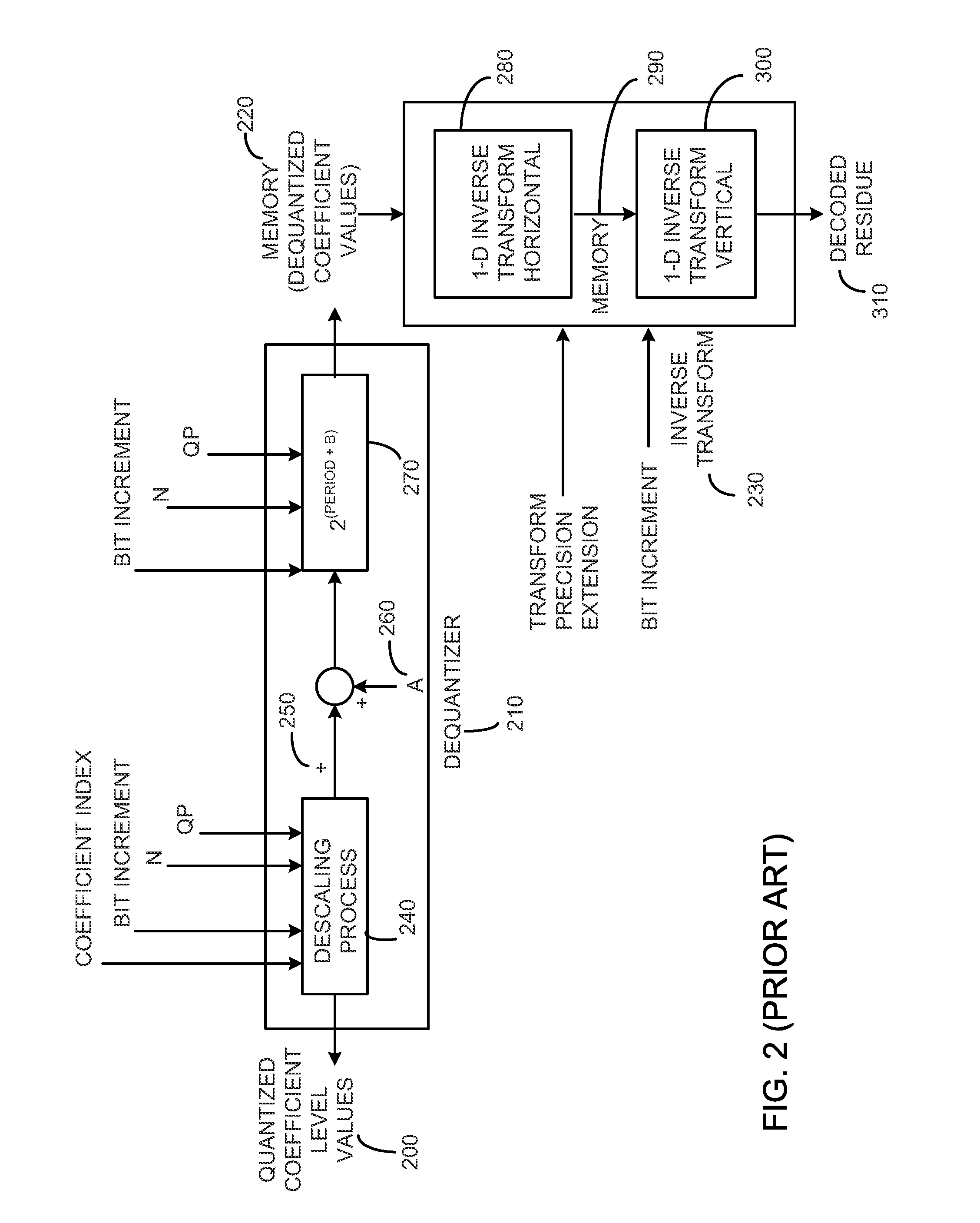
[0016]Referring to FIG. 2 (prior art), a decoder for the de-quantization and inverse transform of the received quantized coefficient level values from the encoder for a block of the image is illustrated, in relevant part. The decoder receives the quantized coefficient level values 200 at a de-quantizer 210. The de-quantized coefficient values resulting from the de-quantizer 210 are stored in memory 220. The de-quantized coefficient values stored in memory 220 are then processed by a pair of inverse transforms 230 to determine a decoded residue 310. The pair of inverse transforms 230 map data from a transform domain to a spatial domain using a matrix multiplication operator or other suitable process. The de-quantized coefficient values 220 and the quantized coefficient level values 200 may be the same, if desired.

[0017]The de-quantizer 210 includes a descaling process 240. The descaling process 240 maps quantized coefficient level values 200 that are transmitted in the bitstream. The...


PUM


Abstract

A system for decoding video including receiving quantized coefficients representative of a block of video representative of a plurality of pixels and dequantizing the quantized coefficients. The system inverse transform the dequantized coefficients using a first one dimensional inverse transform and a second one dimensional inverse transform to determine a decoded residue where the result of the first one-dimensional inverse transform are shifted different amounts using a shifting process based upon the magnitude of the dequantized coefficients.

Description

CROSS-REFERENCE TO RELATED APPLICATIONS[0001]This application is a continuation-in-part of U.S. patent application Ser. No. 13 / 150,541, filed Jun. 1, 2011.BACKGROUND OF THE INVENTION[0002]The present invention relates to image decoding with dynamic range adjustments.[0003]Existing video coding standards, such as H.264 / AVC, generally provide relatively high coding efficiency at the expense of increased computational complexity. As the computational complexity increases, the encoding and / or decoding speeds tend to decrease. Also, the desire for increased higher fidelity tends to increase over time which tends to require increasingly larger memory requirements, increasingly larger memory bandwidth requirements, and increasing hardware complexity. The increasing memory requirements and the increasing memory bandwidth requirements tends to result in increasingly more expensive and computationally complex circuitry, especially in the case of embedded systems.[0004]Referring to FIG. 1, man...

Claims


Application Information

Patent Timeline
IPC IPC(8): H04N7/30
CPCH04N19/132H04N19/18H04N19/625H04N19/48H04N19/44H04N19/184
Inventor KEROFSKY, LOUIS JOSEPHSEGALL, CHRISTOPHER A.MISRA, KIRAN
Owner SHARP KK
Why Eureka
Try Eureka