Battery pack

a battery pack and battery technology, applied in the field of batteries, can solve the problems of compromising the proper operation failure of an element in the battery pack, etc., and achieve the effects of increasing the thermal capacity, and reducing the cost of battery pack maintenan

Inactive Publication Date: 2012-12-06
SANYO ELECTRIC CO LTD
View PDF2 Cites 17 Cited by
  • Summary
  • Abstract
  • Description
  • Claims
  • Application Information

AI Technical Summary

Benefits of technology

[0010]To achieve the above object, a battery pack according to a first aspect of the present invention includes a battery block 10, a main circuit board 40, a heat-generating component 41, a plate-shaped heat-dissipating block 42, and an exterior case 30. The battery block 10 includes a plurality of base batteries 11, and a battery holder 12 having battery accommodation portions 13. Each of the battery 
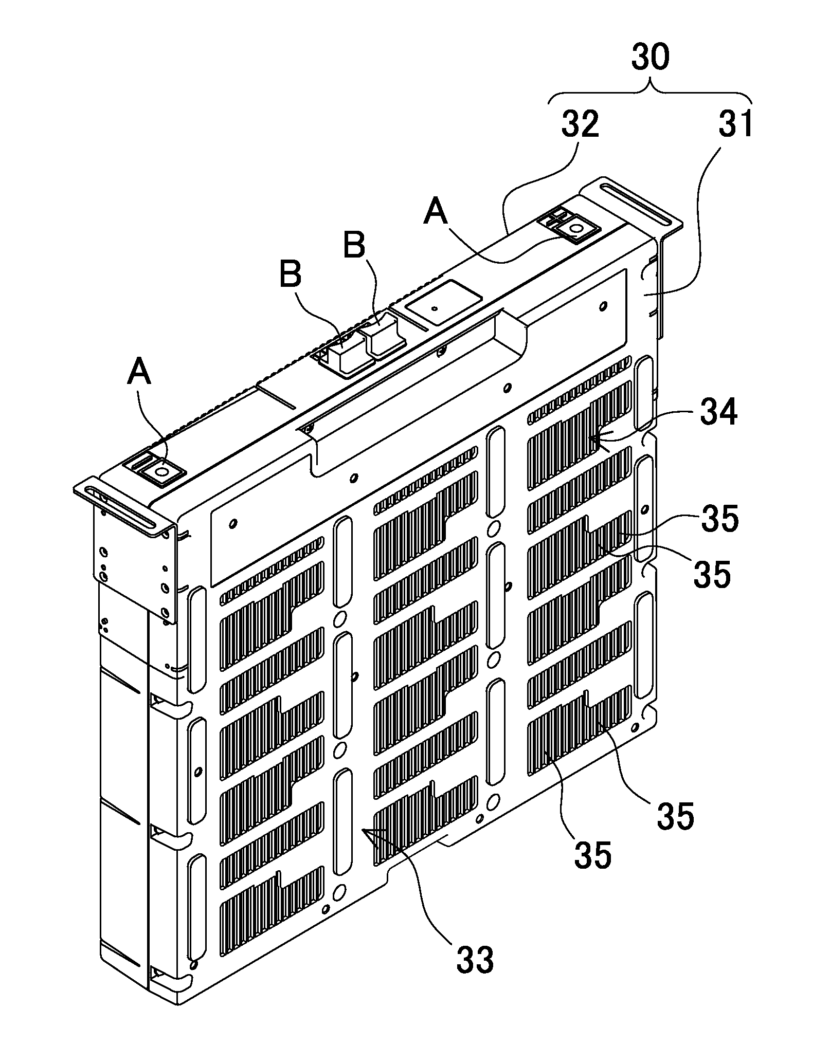
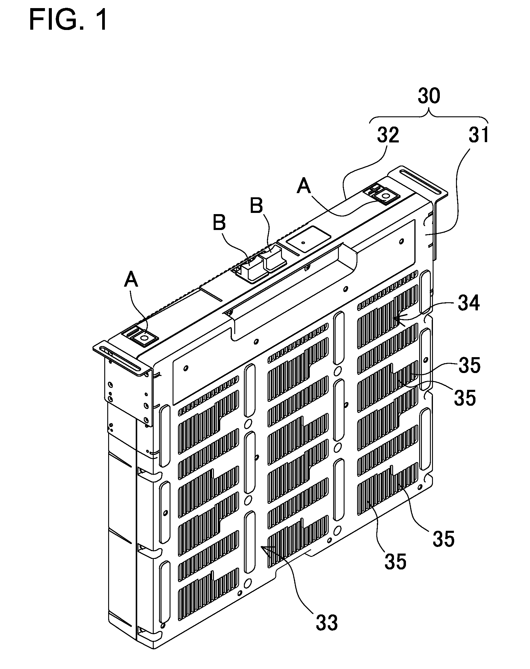
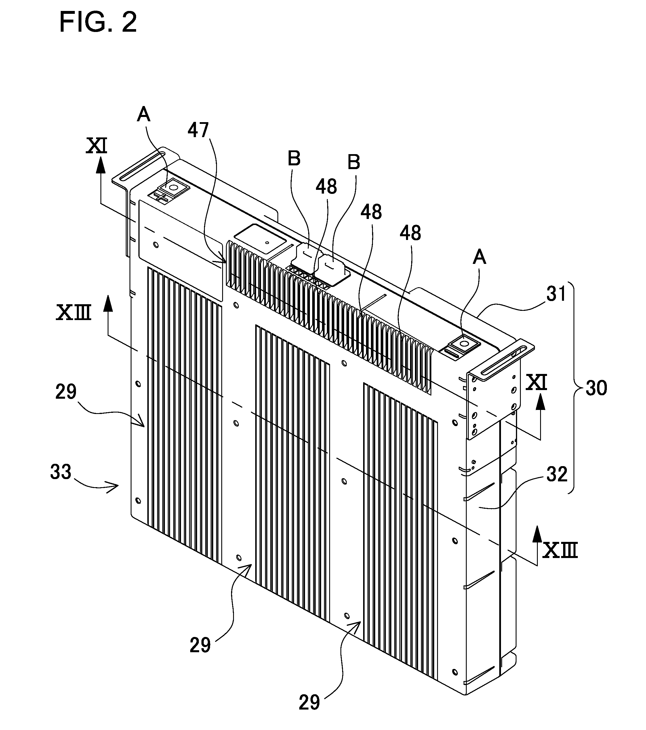
accommodation portions 13 accommodates corresponding one of the plurality of base batteries 11. The main circuit board 40 is connected to the base batteries 11 of the battery block 10. The heat-generating component 41 is connected to the main circuit board 40. The plate-shaped heat-dissipating block 42 is thermally connected to the heat-generating component 41. The exterior case 30 accommodates the heat-dissipating block 42 and the battery block 10. The exterior case 30 includes two opposed surface plates and side walls, and has a box shape. The side walls close peripheral parts of the surface plate 33. The width of the box shape is larger than the thickness of the box shape. The heat-dissipating block 42 is spaced away from the battery block 10 in the exterior case 30 so that the heat-dissipating block 42 does not overlap the battery block 10. The heat-dissipating block 42 is arranged in parallel to the surface plate 33 in the exterior case 30. An opposed surface of the heat-dissipating block 42 opposed to the surface plate 33 is thermally connected to the surface plate 33. Heat generated by the heat-generating component 41 can be conducted to the heat-dissipating block 42 so that the heat can be dissipated from the surface plate 33. According to this construction, the heat-dissipating block can be directly thermally connected to the surface plate of the exterior case. As a result, the exterior case itself can be used for heat dissipation. Therefore, there is an advantage that the heat-dissipating mechanism can be simplified.
[0011]In a battery pack according to a second aspect of the present invention, the heat-dissipating block 42 can be arranged on the longitudinal end side of a plurality of the battery blocks 10.
[0012]In a battery pack according to a third aspect of the present invention, the heat-dissipating block 42 can be a metal block having a thickness of not less than 5 mm. A block recessed portion 44 can be formed in the surface of the heat-dissipating block 42. The heat-generating component 41 can be arranged in and thermally connected to this block recessed portion 44. According to this construction, the heat-dissipating block is thick so that thermal capacity can be increased, and the heat-generating component is enclosed by the block recessed portion. As a result, heat can be efficiently dissipated from the heat-generating component through three enclosing surfaces.
[0013]In a battery pack according to a fourth aspect of the present invention, the main circuit board 40 can be orientated opposed to the recessed portion surface side of the heat-dissipating block 42 where the block recessed portion 44 is formed. The main circuit board 40 can be orientated so that the heat-generating component 41 mounted surface of the main circuit board 40 is opposed to the recessed portion surface side of the heat-dissipating block 42. The heat-generating component 41 is mounted on this heat-generating component 41 mounted surface. According to this construction, the heat-generating component mounted to the main circuit board is arranged in and can be thermally connected to the block recessed portion of the heat-dissipating block.
[0014]In a battery pack according to a fourth aspect of the present invention, the block recessed portion 44 of the heat-dissipating block 42 can be filled with thermally conductive paste 45. According to this construction, since the block recessed portion is filled with the thermally conductive paste so that an air layer can be eliminated between the heat-generating component and the block recessed portion. As a result, a thermally insulating layer can be eliminated. Therefore, the heat-generating component can be thermally connected to the block recessed portion.
[0015]In a battery pack according to a fifth aspect of the present invention, the heat-generating component 41 can include a diode that is serially connected to the base battery 11. This diode can be arranged in the block recessed portion 44 of the heat-dissipating block 42. According to this construction, since a high-heat-generating diode is arranged in the block recessed portion of the heat-dissipating block, the heat can be effectively dissipated.

Problems solved by technology

That is because an abnormal temperature rise of heat-generating component may cause a failure of an element in the battery pack.
Also, an abnormal temperature rise of heat-generating component may compromise proper operation of an element in the battery pack.

Method used


Image

  • Battery pack
  • Battery pack
  • Battery pack

Examples


first embodiment

[0045]The following description will describe a battery pack 100 according to a first embodiment of the present invention with reference to FIGS. 1 to 13. In this embodiment, the present invention is applied to a backup power supply device. FIG. 1 is a perspective view the outward appearance of a battery pack 100 from the front side. FIG. 2 is a perspective view showing the battery pack 100 shown in FIG. 1 as viewed from the back side. FIG. 3 is an exploded perspective view showing the battery pack 100 shown in FIG. 1. FIG. 4 is a perspective view showing the battery pack 100 shown in FIG. 3 with a first case portion 31 being removed. FIG. 5 is a cross-sectional view of the battery pack shown in FIG. 4 taken along the line V-V. FIG. 6 is an exploded perspective view showing accommodated members inside the battery pack 100 shown in FIG. 3. FIG. 7 is a perspective view of a battery block 10. FIG. 8 is an exploded perspective view showing the battery block 10 shown in FIG. 7. FIG. 9 is...


PUM

PropertyMeasurementUnit
thicknessaaaaaaaaaa
thicknessaaaaaaaaaa
thermally conductiveaaaaaaaaaa

Abstract

A battery pack includes a main circuit board 40, and a plate-shaped heat-dissipating block 42. The circuit board 40 is connected to batteries 11 of a battery unit 10. The block 42 is thermally connected to a heat-generating component 41. An exterior case 30 includes two opposed surface plates 33 and side walls that close peripheral parts of the plate 33, and has a box shape the width of which is larger than the thickness. The block 42 is spaced away from the unit 10 in the case 30, and does not overlap the unit 10. The block 42 is arranged in parallel to the plate 33 in the case 30. A surface of the block 42 opposed to the plate 33 is thermally connected to the plate 33. Heat from the component 41 can be conducted to the block 42. The heat can be dissipated from the plate 33.

Description

TECHNICAL FIELD[0001]The present invention relates to a battery pack that includes a battery block including a plurality of rechargeable base batteries accommodated in a battery holder, a heat-generating component connected to the batteries of this battery block, and an exterior case accommodating the battery block and the heat-generating component, and in particular to a battery pack that can efficiently dissipate heat from the heat-generating component.BACKGROUND ART[0002]A battery pack that includes a number of base batteries are connected to each other in series can increase the output voltage. Also, a battery pack that includes a number of base batteries are connected to each other in parallel can increase the output current. These battery packs have heat-generating components including transistors such as FET, and diodes. For this reason, it is important for these battery packs to efficiently dissipate the heat from the heat-generating components. That is because an abnormal t...

Claims


Application Information

Patent Timeline
Patent Type & Authority Applications(United States)
IPC IPC(8): H01M10/42H01M14/00H01M10/60H01M10/613H01M10/627H01M10/653H01M10/6551H01M10/6554H01M50/209H01M50/227H01M50/284
CPCH01M2/1077H01M10/0525H01M10/5067H01M10/5046H01M10/5004H01M10/6563H01M10/6551H01M10/613Y02E60/10H01M50/209H01M50/284H01M50/227
Inventor MIYAMAE, ICHIROUEHARA, YUJIKAWABATA, MASAHIRO
Owner SANYO ELECTRIC CO LTD
Why Eureka
Try Eureka